0 alignment verification with connector leds, Alignment verification with connector leds – MicroE Mercury II 6000 User Manual
Page 20
Alignment Verification with Connector LEDs
IM-Mercury_II_6000 Series Rev. 1
Page 19
©2014 MicroE Systems
Mercury
II
6000 Series Encoders
Installation Manual and Reference Guide
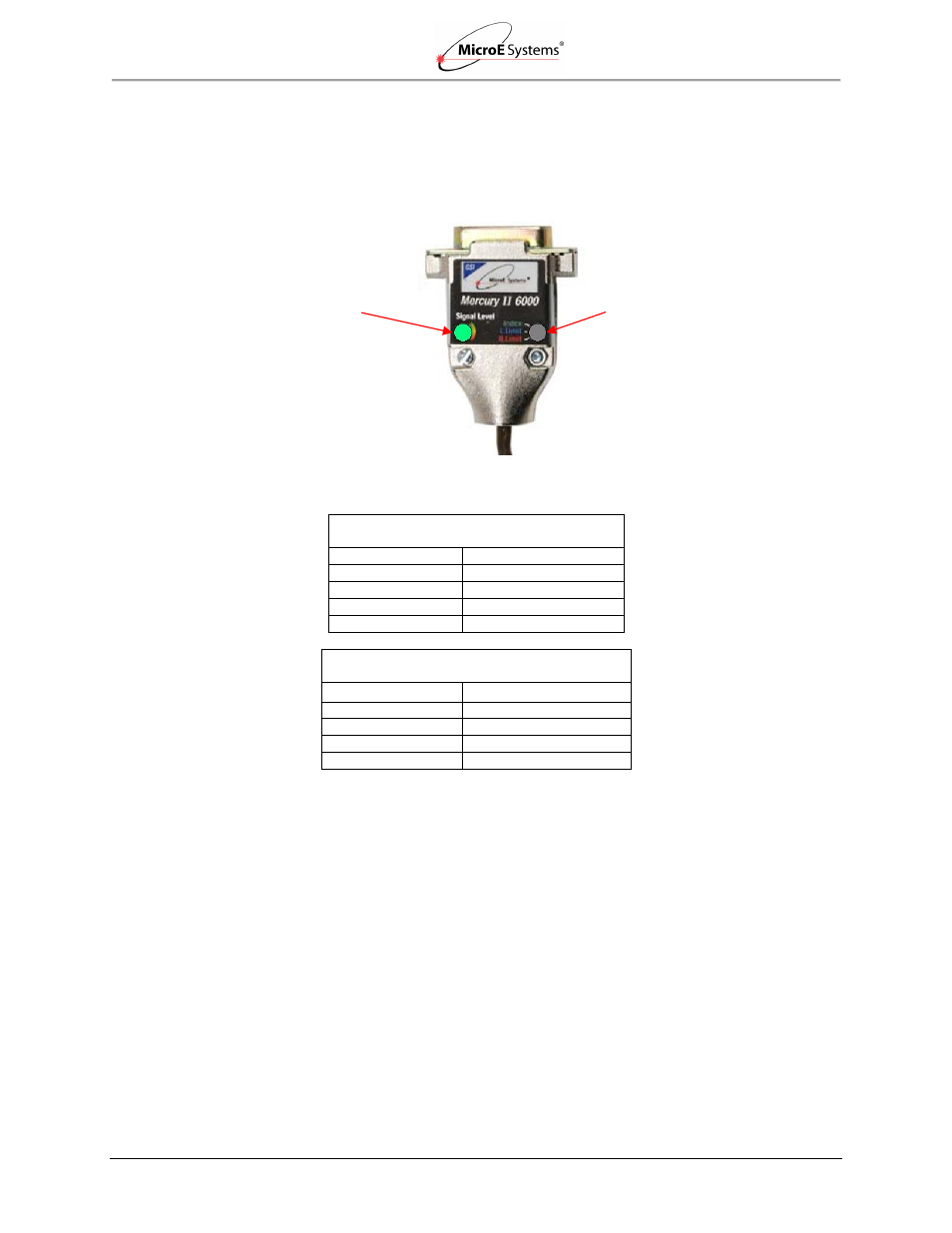
6.0 Alignment Verification with Connector LEDs
Once the encoder is aligned and calibrated using the alignment tool, alignment can be visually
verified using the LED indicators on the MII6000 sensor’s connector.
Sensor Connector display (shown during normal operation):
Color Codes for Indicators
Mercury II Sensor Connectors
LED Indicators
– Signal Strength
Color
Signal Strength
Green
Optimal
Yellow
Marginal
Red
Bad
Purple
Saturated
Mercury II Sensor Connectors
LED Indicators
– Limit/Index Markers
Color
Limit/Index Mark
Green
Over Index Mark
Blue
Over Left Limit Mark
Red
Over Right Limit Mark
None
Not Over Any Mark
Signal Level LED indicates
signal strength of main track
(green is optimal)
Limit/Index LED Indicates presence of
left limit mark, right limit mark, or index
mark (no color indicates sensor not
positioned over any marks)