5 powering the cio-exp-rtd16, 1 power source switch, 2 powering with the 37 pin connector – Measurement Computing CIO-EXP-RTD16 User Manual
Page 9: 3 powering with the c-pcpower-10 cable
3.5 POWERING THE CIO-EXP-RTD16
The CIO-EXP-RTD16 can be powered through the 37-pin cable or the Molex connector. The power that
can be carried through the 37-pin connector is limited so we recommend this only when a single
CIO-EXP-RTD16 is used.
The power required to run a CIO-EXP-RTD16 channel is dependent on the sensor connected to it.
Voltage measurements do not draw additional power from the CIO-EXP-RTD16, but RTDs do for the
excitation current.
3.5.1 Power Source Switch
N
O
4 3 2 1
CU
ST
OM
I
EX
C
+5
R
E
M
X1
IE
X
C
=
1
M
A
+5
C
O
M
P
X7
GND
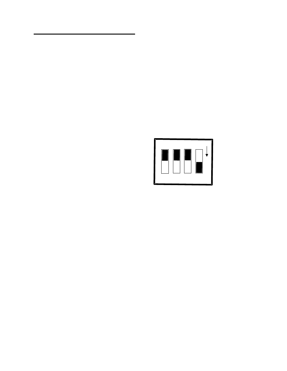
One of the switches on the four-position DIP
switch labeled “2” controls the source of the +5V
power to the CIO-EXP-RTD16.
When positioned down, (+5 COMP), the +5V
power is drawn from the personal computer
through the signal cable. In the +5REM position
(up) power is drawn through the MOLEX
connector.
The right-hand switch selects the source of the
excitation current. The choices are 1 mA source
or a custom current selected by installing a
resistor at R89.
Figure 3-5. Power Source Switch
3.5.2 Powering with the 37 pin connector:
You may power the CIO-EXP-RTD16 via the 37-pin cable. Only one CIO-EXP-RTD16 can be powered
via the 37-pin cable. If you are powering multiple boards, use the C-PCPOWER-10 cable.
3.5.3 Powering with the C-PCPOWER-10 cable:
The CIO-EXP-RTD16 may be powered from the PC's power supply by connecting it to that power supply
through a C-PCPOWER-10 cable. This cable has the same Molex connector that is used inside the PC
and so may be connected directly to the PC's power supply through one of the spare connectors. The
cable is keyed, so it should not be forced. When inserted properly it will slide easily and snap in place.
5