1 first stage gain, 2 second stage gain, Figure 5-2. second stage gain switch location – Measurement Computing CIO-EXP-RTD16 User Manual
Page 18
Base Resistance
Stage 1 Gain
Stage 2 Gain
Total Gain
100 Ohms
8
7
56
1000 Ohms
4
7
28
5.4.1 First Stage Gain
O
N
GAIN
SELECT
CUS
T
O
M
X2
X4
X8
A set of three Gain Select switches on the S1
switch block selects the first stage gain (Figure
4-4). The fourth switch on this block (marked
CUSTOM) is used to select a custom second
stage gain.
When all three switches are up, the first stage
gain is 1. Moving a switch down (ON) selects
that gain. The other two switches should be up.
(Gains choices for the first stage are NOT
additive.)
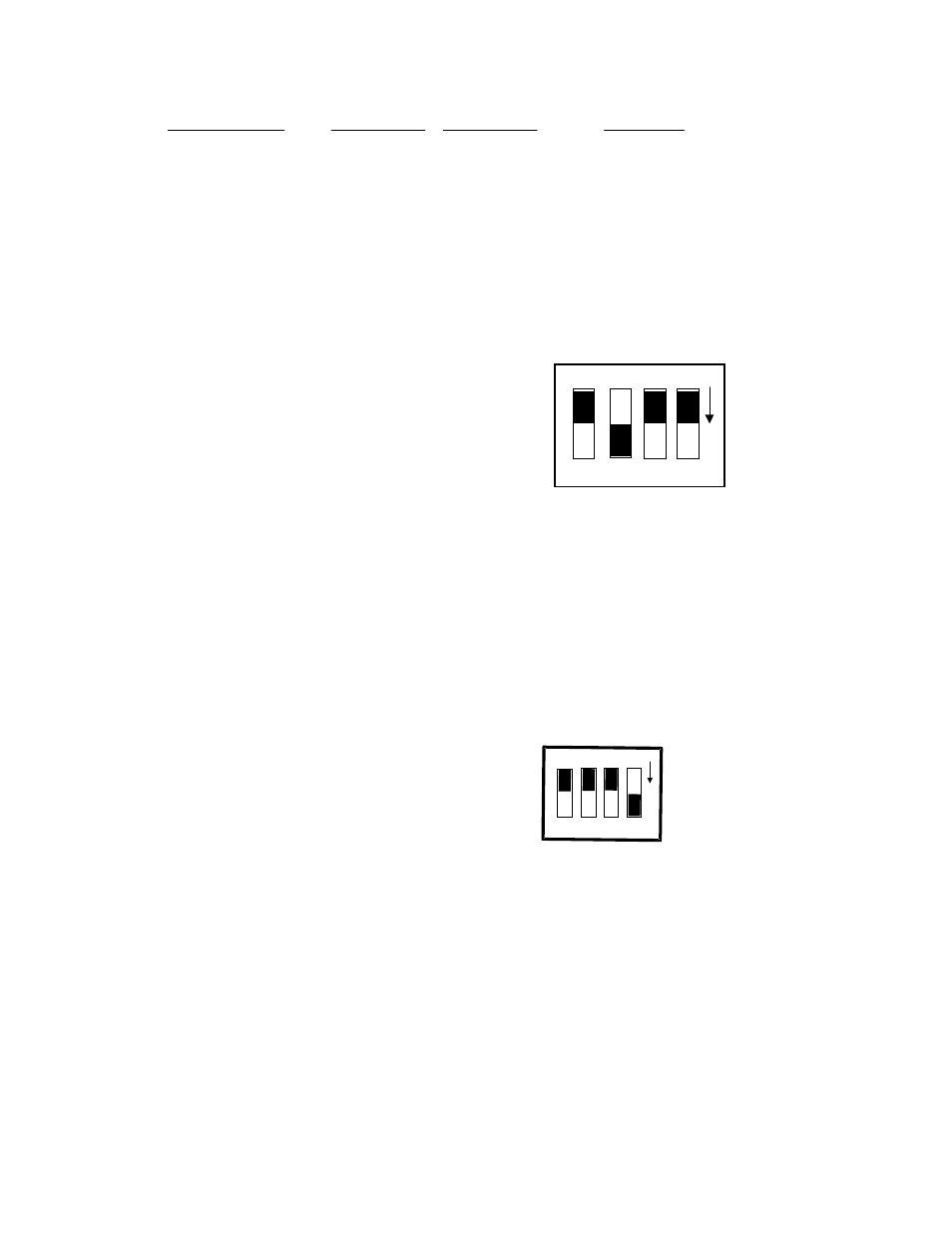
Thus, gains of 1, 2, 4 or 8 can be selected by
these switches. A gain of X2 is shown in Figure
5-1.
Figure 5-1. First Stage Gain Select Switches
5.4.2 Second Stage Gain
N
O
4 3 2 1
C
U
ST
OM
I
EXC
+5 R
E
M
X1
IE
X
C
=
1
M
A
+5
C
O
MP
X7
GND
Switch #3 on the S2 DIP switch block (Figure
5-2) is labeled X1 and X7. Setting this switch
down (ON) will amplify the output of the first
stage amplifier by 7. The factory default
position (up) has a gain of 1 (unity).
When set to X7, the first stage gain is
multiplied by 7 yielding overall gains of 7, 14,
28 or 56.
A second stage gain of 7 is recommended for
RTD applications.
Figure 5-2. Second Stage Gain Switch Location
A custom second stage gain of greater than 7 and less than 64 may be added by installing a precision
resistor at RX100 and setting the switch marked CUSTOM on.
When using the custom second stage gain, set the switch marked CUSTOM on the S1 bank to the ON
position (down) and set the X7 switch on the S2 bank to X1. Install a precision resistor of the
appropriate value in the RX100 location. Calculate the value using the formula found in the Custom
Gain and Excitation Calculations chapter.
14