4 setting the gain 4.4.1 first stage gain switch, 2 second stage gain switch – Measurement Computing CIO-EXP-RTD16 User Manual
Page 12
To choose a switch-selectable amplification, calculate as follows:
If your signal is bipolar, divide 10 by the full range of the signal. For example, if your signal ranges
between ±1/2 volt, the full range is 1 volt. Divide 10 by 1 for a result of 10. That is the maximum gain
you can use.
If your signal is unipolar and ranges less than 0 to 5V, divide 5 by the full range of the signal. For
example, if the signal ranges from 0 to 1/2 volt, the full range is 1/2 volt. Divide 5 by 0.5 for a result of
10. That is the maximum gain you can use.
4.4 SETTING THE GAIN
4.4.1 First Stage Gain Switch
O
N
GAIN
SELECT
CUS
T
O
M
X2
X4
X8
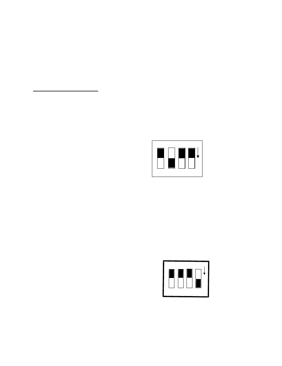
A set of three Gain Select switches on the
S1 switch block selects the first stage gain
(Figure 4-1). The fourth switch on this
block (marked CUSTOM) is used to select
a custom second stage gain.
When all three switches are up, the first
stage gain is 1. Moving a switch down
selects that gain. The other two switches
should be up. (Gains choices for the first
stage are NOT additive.)
Thus, gains of 1, 2, 4 or 8 can be selected
by these switches. A gain of X2 is shown in
Figure 4-1.
Figure 4-1. First Stage Gain Select Switches (S1)
4.4.2 Second Stage Gain Switch
N
O
4 3 2 1
CUST
O
M
IEXC
+5
R
E
M
X1
IE
XC
=
1
MA
+
5
C
OMP
X7
GND
Switch #3 on the S2 DIP switch block (Figure
4-2) is labeled X1 and X7. Setting this switch
down (ON) will amplify the output of the first
stage amplifier by 7. The factory default position
(up) has a gain of 1 (unity).
When set to X7, the first stage gain is multiplied
by 7 yielding overall gains of 7, 14, 28 or 56.
A custom second stage gain of greater than 7 and
less than 64 may be added by installing a
precision resistor at RX100 and setting the switch
marked CUSTOM on.
Figure 4-2. Second Stage Gain Switch (#3 of S2)
8