Caution – Measurement Computing CIO-EXP-RTD16 User Manual
Page 14
+I
E
X
C
+S
EN
S
E
−
IE
X
C
−
SE
N
S
E
CH0
Voltage
Source
Add Jumper
Single-Ended Voltage Input
Signal-High
Signal-Low
(Gnd.)
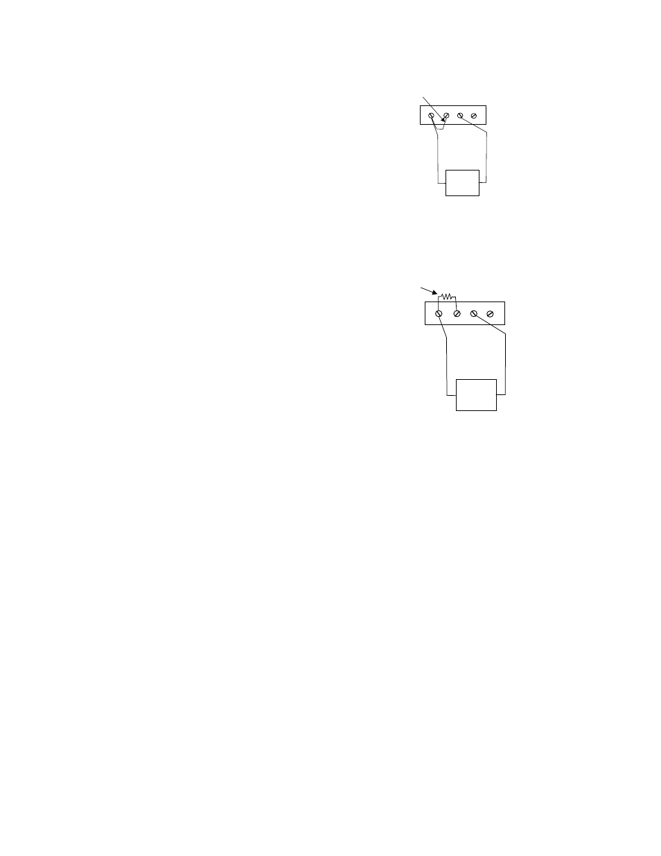
Each input circuit has four screw terminals associated with it.
These terminals are shown in Figure 4-5 to the right.
To connect a voltage signal to the input circuit you only use
three screw terminals; these are:
+SENSE Signal high, or CH HI on a DAS board
-SENSE Signal low, or CH LO on a DAS board
-IEXC Low Level Ground (LLGND)
Figure 4-5. Single-Ended Voltage Input
4.7.2 Floating
Differential
A floating differential input has two wires from the
signal source and a 10K ground reference resistor
installed at the CIO-EXP-RTD16 input. The two
signals from the signal source are Signal High and
Signal Low. The reference resistor is connected
between the CIO-EXP-RTD16 -SENSE and -IEXC
pins (Figure 4-6).
A floating differential hookup is handy when the signal
source is floating with respect to ground, such as a
battery-powered device. The floating differential input
will reject up to 10V of EMI energy on the signal
wires.
Figure 4-6. Floating-Differential Voltage Input
CAUTION
:
Verify that the signal source is really floating. Check it with a voltmeter before risking the
CIO-EXP-RTD16 and PC!
10
+I
E
X
C
+S
E
N
S
E
−
IE
X
C
−
SE
NSE
Voltage
Source
Add 10K
Resistor
Floating-Differential Voltage Input
Signal-High
Signal-Low