5 attenuation, 6 channel configuration switch, 1 single ended – Measurement Computing CIO-EXP-RTD16 User Manual
Page 13
When using the custom second stage gain, set the switch marked CUSTOM on the S1 bank to the ON
position (down) and set the X7 switch on the S2 bank to the ON position (X7). Install a precision
resistor of the appropriate value in the RX100 location. Calculate the value using the formula found in
the Custom Gain and Excitation Calculations chapter.
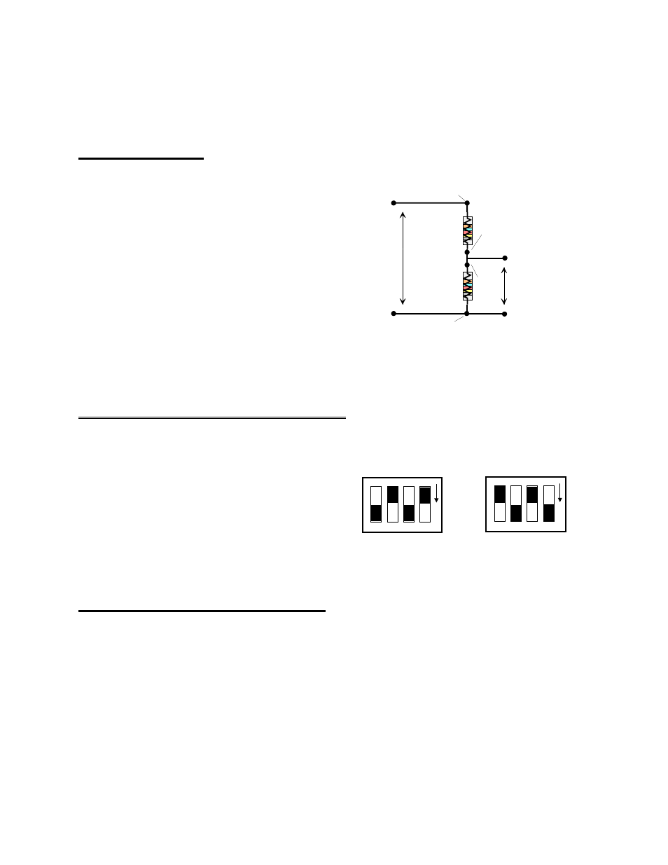
4.5 ATTENUATION
Volts In
Volts Divided
Ra
Rb
RES IN
RES
IN
RES OUT
RES
OUT
INPUT
PC GROUND
OUT
PC GROUND
If your signal range is greater than ±5V, you
will have to divide it until the result is less than
or equal to ±5V for bipolar, or 0-5V for
unipolar signals.
A voltage divider is constructed from a pair of
precision resistors selected according to the
equation:
Attenuation = (R1 + R2) / R2
You will need to construct the voltage divider
remote from the CIO-EXP-RTD16.
Figure 4-3. Voltage Divider Schematic
4.6 CHANNEL CONFIGURATION SWITCH
3
4
3
4
O
N
INPUT CONFIG
3
4
3
4
O
N
0
1
Set for 2 or 4-Wire Connection
Set for 3-Wire Connection
A channel configuration switch is associated with
each channel. The switch is used to configure the
input circuit for 2, 3 or 4-wire hookup to RTDs.
NOTE: When doing voltage measurements, set
the switches to the 4-wire position (switches
labeled “4” in white on the board in the ON
position - switches labeled “3” OFF).
Figure 4-4. Channel Configuration Switches
4.7 CONNECTING VOLTAGE SIGNALS
Voltage signals may be single ended or differential, and the full scale may have to be matched to the
range of the CIO-EXP-RTD16 and DAS board combination via amplification or division. To connect a
voltage and make an accurate measurement, each of these factors must be considered.
4.7.1 Single Ended
A single-ended input has two wires; a signal high and a Ground (
−
IEXC). The Low Level Ground signal
must be the same ground the PC is on. Single-ended mode is selected by installing a jumper between the
signal input low and ground (
−
SENSE to
−
IEXC) (Figure 4-5).
9