Measurement Computing STLITE-CPCI-xxx User Manual
Page 15
11
To add or remove traces from the strip charts, select the Data Sources item under the Format menu, and select or
deselect the checkboxes corresponding to the desired traces.
6.3
WATCH DOG TIMER AND ALARM
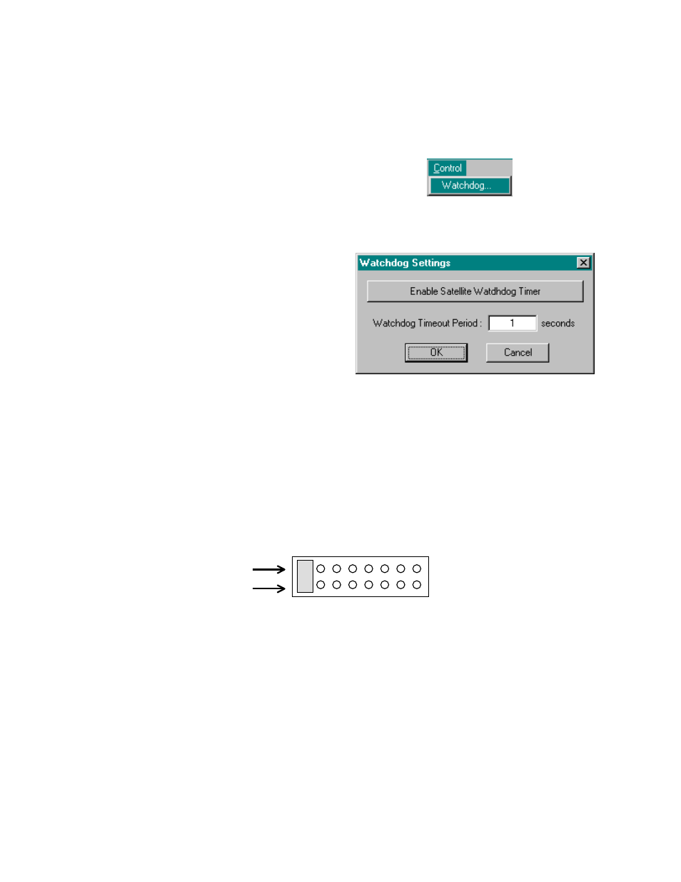
Figure 6-7. Control Menu
Figure 6-8. Watchdog Timer Settings Display
The Expansion card located in the rear of the STLITE chassis offers some useful features for event monitoring
and control. All access to the watchdog timer and alarm features is via the P3 header located on the top-right
portion of the Expansion card. In operation, the watchdog timer will repeatedly assert a timeout signal at the end
of the selected period. When enabled, this timeout signal is used to assert the Alarm_Out and Alarm_Out/n
signals. In addition, the Alarm_Out signal provides control of an undedicated SPDT relay. In the Alarm state
(timer expired) the relay closes, otherwise it is in the open position.
It is necessary to remove the top cover of the unit to access these features. Using a Torx T-10 driver, loosen the
four retaining screws and lift off the cover. Do not remove the screws.
A diagram and pinout of the P3 header is shown below in Figure 6-9.
Figure 6-9. P3 Header
To enable or disable the watchdog timer, select
Watchdog… under the Control menu (Figure 6-7).
Set the Watchdog Timeout Period to match that of
the hardware settings. Click the button labeled
“Enable Satellite Watchdog Timer” to enable the
watchdog (Figure 6-8).
After being enabled, the button will read “Disable
Satellite Watchdog Timer.” Clicking on the button
labeled “Disable Satellite Watchdog Timer” will
disable the watchdog timer and set the button label
to read "Enable Satellite Watchdog Timer.”
Note that the watchdog timer may alarm even under
proper operation if the timeout period entered in the
dialog is more than twice its hardware settings.
Pin 1
Pin 2