Host pci/cpci computer, Daisy-chained stlite-cpci-8r/16r expansion racks – Measurement Computing STLITE-CPCI-xxx User Manual
Page 10
6
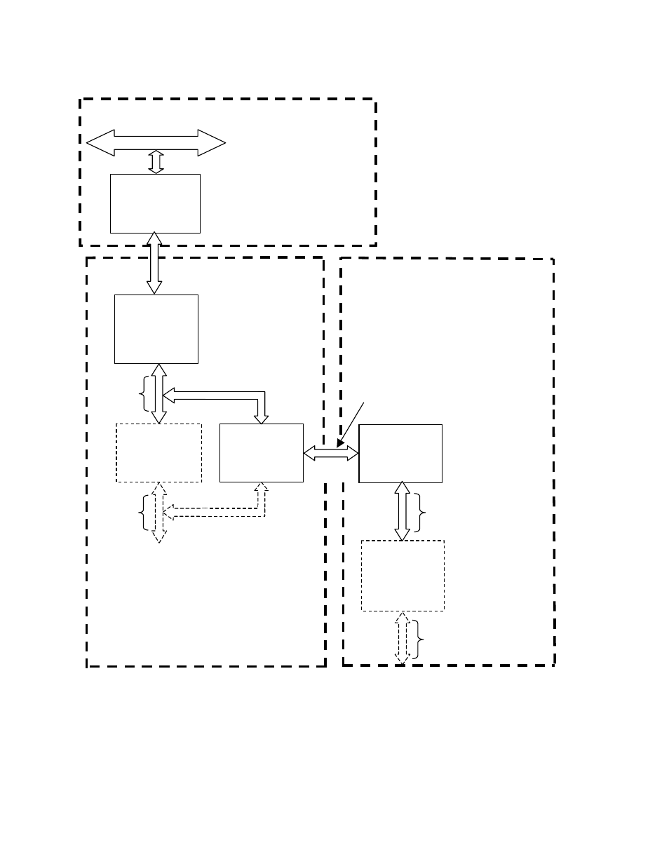
either Bus 3 or 4. Thus, the first PPB in the second expansion rack will have its primary attached to Bus 3 or 4
its secondary will be motherboard’s Bus 4 or 5. A 16-slot rack will have its second bus as number 5 or 6.
Figure 5-1. CPCI Expansion Daisy Chaining
Host
Bridge
Bus 1
Bus 0
Host PCI
Bridge
2
nd
Rack
Bus 1
Bus 2
(Board)
First
PCI Bridge
Bus 2
Second
PCI Bridge
(16-slot rack)
(Cable)
Bus 3
(Board)
Alternate Attachment to Bus 3
(for STLITE-CPCI-16R only)
Attachment to STLITE-CPCI-8R, or
Alternate for STLITE-CPCI-16R
STLITE-CPCI-8R/16R
Daisy-Chained, 2nd
STLITE-CPCI-8R/16R
(Cable)
Bus 3 or 4*
Bus 4 (or 5)
(Board)
First
PCI Bridge
Second
PCI Bridge
(16-slot rack)
Bus 5 (or 6)
(Board)
Host
PCI/CPCI
Computer
*If the 2
nd
Host CPCI bridge is connected to Bus
2 (in either an 8- or 16-slot rack), its cable will be
Bus 3. But, if connected to the second bus (#3)
in a 16- slot rack, its cable will be Bus 4.
Board bus number(s) will vary accordingly.
8 slots
8 slots
8 slots
8 slots
Daisy-Chained STLITE-CPCI-8R/16R Expansion Racks