Host pci/cpci computer – Measurement Computing STLITE-CPCI-xxx User Manual
Page 11
7
5.3
FAN-OUT CONFIGURATION
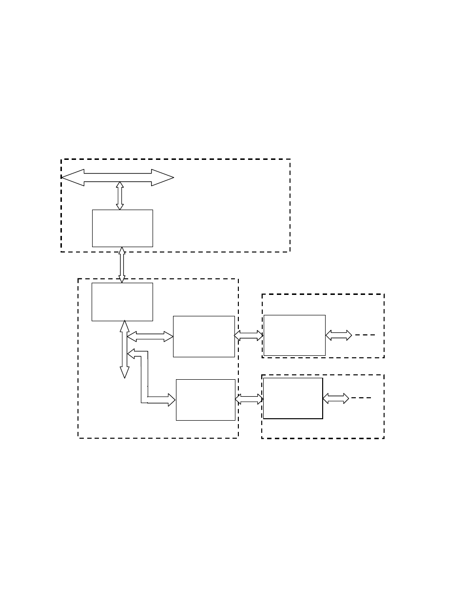
In this configuration, the Host Bridge card for a second CPCI chassis is inserted in an open slot in the first
expansion rack. The Host Bridge card for the first rack is inserted in an open slot of the host computer as usual.
The first and second expansion racks have bus level numbers identical with the daisy chain configuration
described above.
Adding a third expansion chassis (PPB) to Bus 2 is the fan-out (parallel) configuration (Figure 5-2).
NOTE: Although we have numbered the second chassis to extend from Bus 2 as “Bus 6”, logically, it is at the
same hierarchical level as Bus 4 since it is attached to Bus 2.
Figure 5-2. CPCI-Expansion-Serial/Parallel Configuration for Rack-Mounted Units
Bus 3
(Cable)
Host
Bridge
First Rack
PCI Bridge
Second Rack
PCI Host
Bridge
Third Rack
CPCI Host
Bridge
Bus 0
Bus 1
(Cable)
Bus 2
(8 slots)
Bus 2
Bus 5
(Cable)
Second Rack
PCI Bridge
Third Rack
PCI Bridge
Bus 2
Bus 4
(8 slots)
Bus 6
(8 slots)
STLITE-CPCI-8R/16R
STLITE-CPCI-8R/16R
STLITE-CPCI-8R/16R
HOST
PCI/CPCI
COMPUTER
Fan-Out Configuration – Satellite CPCI Expansion System