Interrupt, Counter – Measurement Computing PC-CARD-DAS16/330 User Manual
Page 22
PC-CARD-DAS16/330 User's Guide Specifications
Interrupt
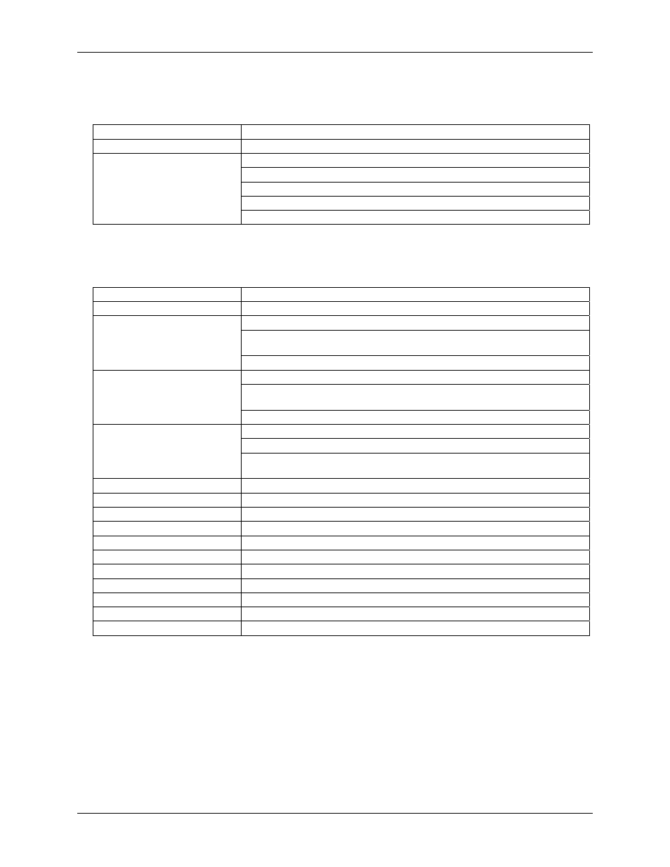
Table 7. Interrupt specifications
Interrupts
Programmable: levels 2 – 15
Interrupt enable
Programmable (default = disabled)
External (External Interrupt)
A/D End-of-channel-scan
A/D FIFO-not-empty
A/D FIFO-half-full
Interrupt sources
A/D Pacer
Counter
Table 8. Counter specifications
Counter type
82C54
Configuration
3 down counters, 16 bits each
Source:
Programmable external (Ctr 1 Clk) or 100kHz internal source
Gate:
Available at connector (Ctr 1 Gate), pulled to logic high via 10k
resistor (See Note 2).
Counter 1 - User counter
Output:
Available at connector (Ctr 1 Out)
Source:
Programmable, 1 MHz or 10 MHz internal source
Gate:
Available at connector (A/D Pacer Gate), pulled to logic high via
10 k resistor.
Counter 2 - ADC Pacer Lower
Divider
Output:
Chained to Counter 3 Clock
Source:
Counter 2 Output
Gate:
Internal
Counter 3 - ADC Pacer Upper
Divider
Output:
Programmable as ADC Pacer clock. Available at user connector
(ADC Pacer out)
Clock input frequency
10 MHz max
High pulse width (clock input)
30 ns min
Low pulse width (clock input)
50 ns min
Gate width high
50 ns min
Gate width low
50 ns min
Input low voltage
0.8 V max
Input high voltage
2.0 V min
Output low voltage
0.4 V max
Output high voltage
3.0 V min
Crystal oscillator frequency
10 MHz
Frequency accuracy
50 ppm
Note 2:
If you are not driving the gate of User Counter 1, it is strongly recommended that it be connected
to +5V (VDD).
22