Cabling – Measurement Computing PC-CARD-DAS16/330 User Manual
Page 13
PC-CARD-DAS16/330 User's Guide
Installing the PC-CARD-DAS16/330
Cabling
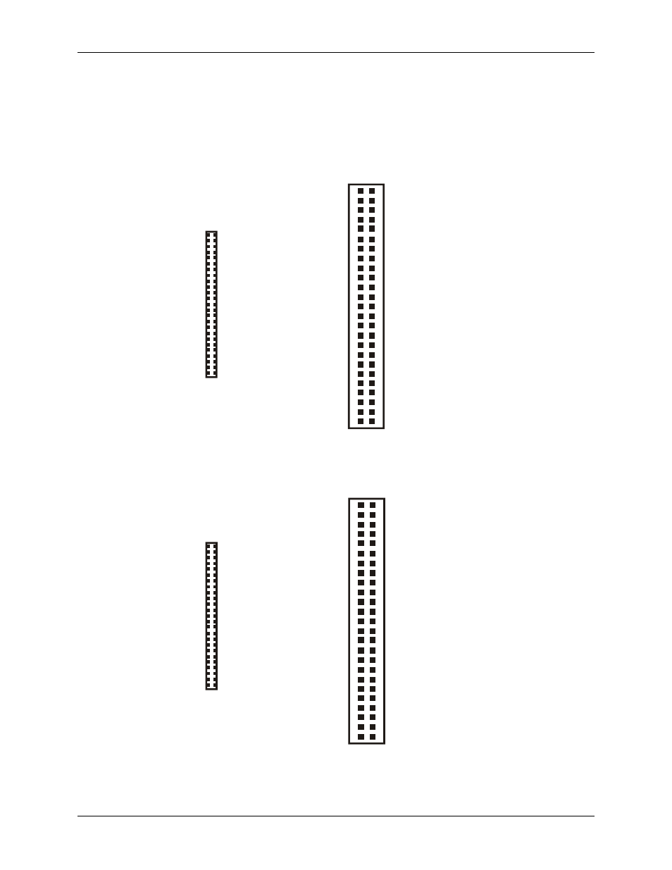
Measurement Computing offers two cables for connecting the PC-CARD-DAS16/330 to a screw-type terminal
board or other signal conditioning interface board:
The CPCC-50F-39 cable: 39 inches (990 mm) long; compatible with standard 50-pin screw terminal
products.
The CPCC-50M-4 cable: four-inch long adapter cable; required when using a C50FF-x series cable.
1
50
PC-CARD end
CPCC-50M-4 cable end
(connect to C50FF-x)
CH0 IN
CH1 IN
CH2 IN
CH3 IN
CH4 IN
CH5 IN
CH6 IN
CH7 IN
AGND
N/C
N/C
N/C
DGND
DIO1
DIO3
DIO5
DIO7
N/C
N/C
CTR1 GATE
A/D External Pacer
A/D Pacer Gate
N/C
+5V Power
DGND
AGND
CH8 IN
CH9 IN
CH10 IN
CH11 IN
CH12 IN
CH13 IN
CH14 IN
CH15 IN
N/C
N/C
N/C
N/C
DIO0
DIO2
DIO4
DIO6
N/C
N/C
CTR1 CLK
CTR1 OUT
External Interrupt
A/D External Trigger
A/D Pacer Out
N/C
1
3
5
7
9
11
13
15
17
19
21
23
25
27
29
31
33
35
37
39
41
43
45
47
49
2
4
6
8
10
12
14
16
18
20
22
24
26
28
30
32
34
36
38
40
42
44
46
48
50
Figure 4. Cable map — PC-CARD to CPCC-50M-4
CPCC-50F-39 cable end
(connect to screw terminal or relay boards)
1
3
5
7
9
11
13
15
17
19
21
23
25
27
29
31
33
35
37
39
41
43
45
47
49
2
4
6
8
10
12
14
16
18
20
22
24
26
28
30
32
34
36
38
40
42
44
46
48
50
CH0 IN
CH1 IN
CH2 IN
CH3 IN
CH4 IN
CH5 IN
CH6 IN
CH7 IN
AGND
N/C
N/C
N/C
DGND
DIO1
DIO3
DIO5
DIO7
N/C
N/C
CTR1 GATE
A/D External Pacer
A/D Pacer Gate
N/C
+5V Power
DGND
AGND
CH8 IN
CH9 IN
CH10 IN
CH11 IN
CH12 IN
CH13 IN
CH14 IN
CH15 IN
N/C
N/C
N/C
N/C
DIO0
DIO2
DIO4
DIO6
N/C
N/C
CTR1 CLK
CTR1 OUT
External Interrupt
A/D External Trigger
A/D Pacer Out
N/C
1
50
PC-CARD end
Figure 5. Cable map — PC-CARD to CPCC-50F-39
13