Specifications, Analog input, Accuracy – Measurement Computing PC-CARD-DAS16/330 User Manual
Page 20: Chapter 5
Chapter 5
Specifications
Typical for 25 °C unless otherwise specified.
Specifications in italic text are guaranteed by design.
Analog input
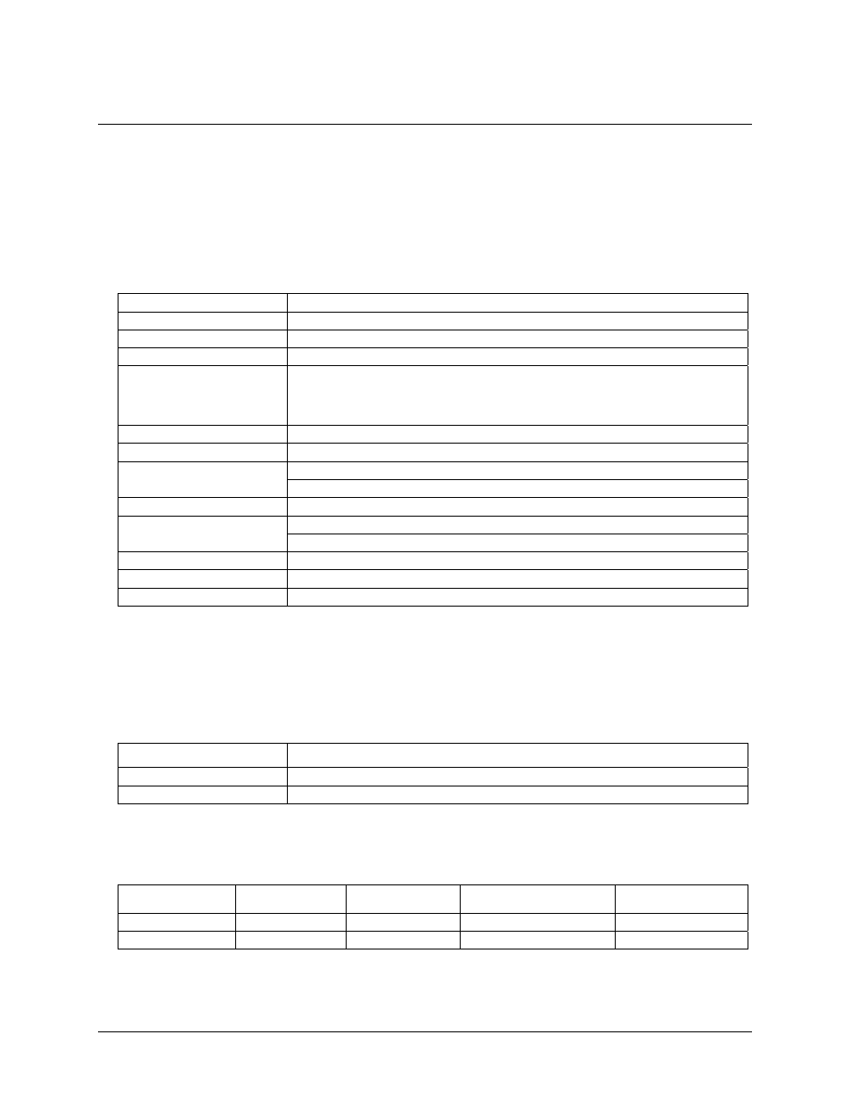
Table 1. Analog input specifications
A/D converter type
ADS7800
Resolution 12
bits
Number of channels
16 single-ended
Input ranges
±10 V, ±5 V - software programmable
A/D pacing
(software programmable)
Internal counter - 82C54
External source - A/D External Pacer,
software programmable for rising or falling edge
Software polled
A/D trigger sources
External edge trigger (A/D External Trigger)
A/D triggering modes
Rising or falling edge trigger - software selectable
A/D External Trigger, gate high or low, software selectable
A/D gate sources
A/D Pacer Gate, gate high
Burst mode
Software selectable option, burst rate = 333 kHz
From 4 k sample FIFO via REPINSW
Data transfer
Programmed I/O
A/D conversion time
3 µs max
Calibrated throughput
330 kS/s, minimum system requirement is Pentium II, 400 MHz.
Calibration
Auto-calibration, calibration factors for each range stored on board in nonvolatile RAM
Accuracy
Accuracies are listed for a 333 kS/s sampling rate, single channel operation, a 60 minute warm-up, and
operational temperatures within ±2 °C of internal calibration temperature. The calibrator test source high side is
tied to Channel 0 In and the low side tied to AGND.
Table 2. Absolute accuracy specifications
Range Absolute
Accuracy
±10.000 V
±3.0 LSB
±5.000 V
±3.0 LSB
Each PC-CARD-DAS16/330 is tested at the factory to assure the board’s overall error does not exceed
accuracy limits described in Table 2.
Table 3. Calibrated accuracy components (LSB)
Range
Gain Error
Offset Error
DLE
(Note 1)
ILE
(Note 1)
±10.00 V
±1.0 max
±1.0 max
±1.0 max
±1.0 max
±5.000 V
±1.0 max
±1.0 max
±1.0 max
±1.0 max
Note 1:
These are the intrinsic specifications of the ADC. Software calibration may introduce a small
additional amount of linearity error.
20