Measurement Computing CIO-DAS16/M1/16 User Manual
Page 18
RCG - Residual Counter Gate. 0 = disabled, 1 = enabled. The Residual Counter Gate gates Counter 0 'on' to allow the
software to count the residual number of samples taken off the FIFO in REP INSW mode.
FFNE - FIFO Not Empty. 0 = FIFO is not empty - contains A/D data, 1 = FIFO is empty.
UNI/BIP - A/D input Unipolar/Bipolar mode select. 0 = Bipolar mode, 1 = Unipolar mode.
G1:0 - A/D input Gain setting.
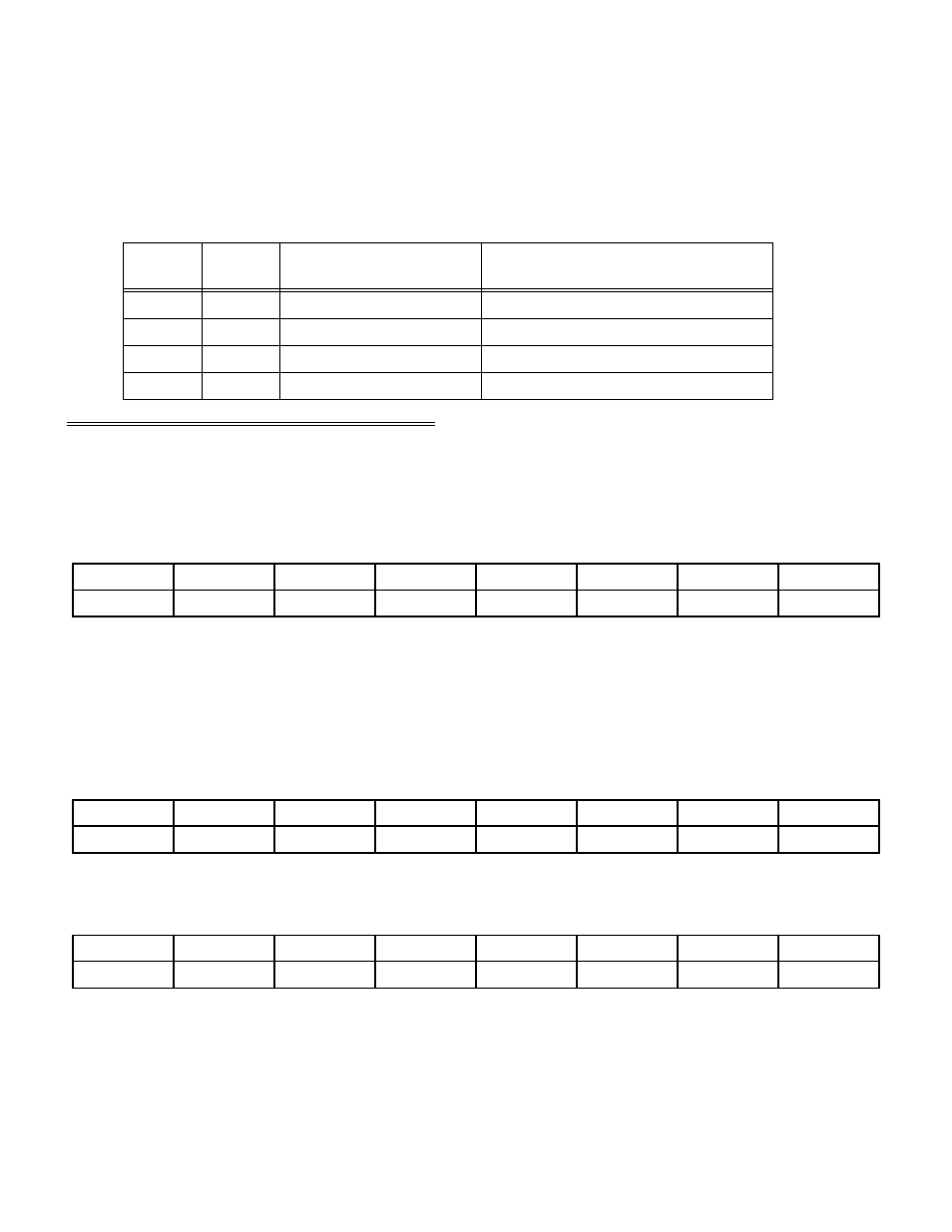
Table 5-4. Analog Input Range/Gain Coding
0 to 1.25V or ±.625V
8
1
1
0 to 2.5V or ±1.25V
4
0
1
0 to 5V or ±2.5V
2
1
0
0 to 10V or ±5V
1
0
0
ANALOG INPUT VOLTAGE
RANGE
ANALOG INPUT GAIN
G0
G1
5.9 8254 DATA AND CONTROL REGISTERS
5.9.1
8254 COUNTER 0 DATA - GENERAL PURPOSE OR RESIDUAL COUNTER
BASE + 12
Example, 30Ch, 780 decimal
READ/WRITE
D1
D2
D3
D4
D5
D6
D7
D8
0
1
3
2
4
5
6
7
In default mode, Counter 0 is a general purpose counter supplied to the user. When REP INSW conversions are
performed and the user sets Enhanced Mode, Counter 0 becomes a residual counter (See register Base + 11 for further
description).
*NOTE: Total count must be greater than 512 for the residual counter to work correctly.
6.9.2
8254 COUNTER 1 DATA - PACER DIVIDER LOWER
BASE + 13
Example, 30Dh, 781 decimal
READ/WRITE
D1
D2
D3
D4
D5
D6
D7
D8
0
1
3
2
4
5
6
7
6.9.3
8254 COUNTER 2 DATA - PACER DIVIDER UPPER
BASE + 14
Example, 30Eh, 782 decimal
READ/WRITE
D1
D2
D3
D4
D5
D6
D7
D8
0
1
3
2
4
5
6
7
Counter 2 is the lower 16 bits of the 32-bit pacer clock divider. It's output is fed to the clock input of Counter 2 which
is the upper 16-bits of the pacer clock divider. The clock input to Counter 1 is a 10 MHz precision oscillator source.
Counter 2's output is called the 'Internal Pacer' and can be selected by software to be the A/D Pacer source. Counters
1 and 2 should be configured to operate in 8254 Mode 2.
14