Measurement Computing CIO-DAS16/M1/16 User Manual
Page 14
READ
On read, the 16-bit ADC value is presented in 'left-justified' format, with the most-significant ADC bit at position
#15; the least significant ADC bit at position #0 of the data word.
WRITE
A write to the base address causes an A/D conversion, (Bits “0” and “1” of BASE+9 must be “0”.)
Also, the write to base address acts as an Internal Trigger to start conversions if the method of converting is External
or Internal Pacer.
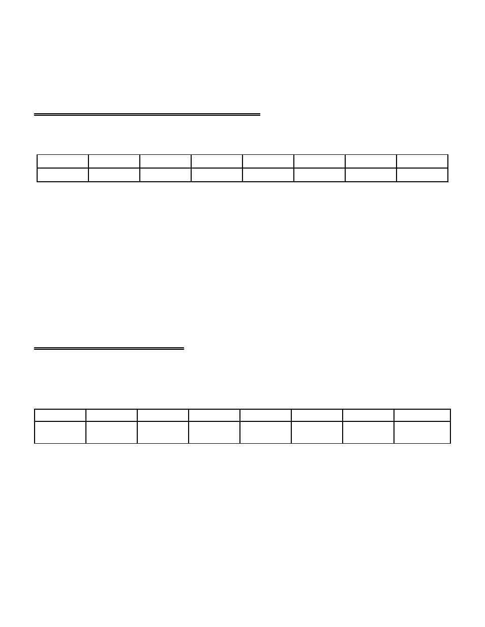
5.3 CHANNEL MUX HI/LO LIMITS WORD REGISTER
BASE ADDRESS +2
Example, 302h, 770 Decimal
CH1L
CH2L
CH4L
CH8L
CH1H
CH2H
CH4H
CH8H
0
1
3
2
4
5
6
7
This register functions the same as DAS1600 products in 8-channel differential mode. The channel mux setting is
written and read from in this register. To configure the channels to convert, the upper nibble sets the high channel and
the lower nibble sets the low channel.
For example:
- To sample channel 1 only, write 11h to BASE+2
- To sample channels 0 to 2, write 20h to BASE+2
- To sample channels 5 and 6, write to 65h to BASE+2
WRITE
Sets the channel mux and resets the FIFO.
READ
Reads the current channel mux which the A/D will convert on the next trigger pulse.
5.4 8-BIT DIGITAL I/O REGISTERS
BASE ADDRESS +3 Example, 303h, 771 Decimal
READ
DI0
ExtPacer
DI1
ExtTrig
DI2
GATE0
DI3
0
0
1
1
0
1
3
2
4
5
6
7
The four digital inputs and the upper nibble of the board ID are read as one byte. Three of the pins have special
functions in addition to being digital input pins. They are:
O ExtPacer/DI0
External Pacer: Single A/D conversion on each active edge.
O ExtTrig/DI1
External Trigger/Gate: Starts Pacer (Internal/External) which generates A/D Conversions on
each active edge of pacer.
O GATE0/DI2
Gate for CTR0. Used to Gate Counter 0.
10