Screw terminal connector type and pin out – Measurement Computing WEB-TC User Manual
Page 34
WEB-TC User's Guide
Specifications
34
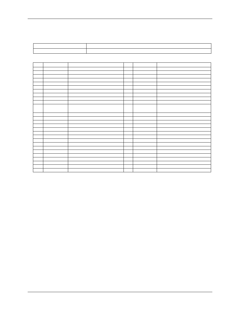
Screw terminal connector type and pin out
Table 19. Screw terminal connector specifications
Connector type
Screw terminal
Wire gauge range
16 AWG to 30 AWG
Table 20. Screw terminal pin out
Pin Signal Name
Pin Description
Pin
Signal Name
Pin Description
1
RSVD
Reserved - see Note 10
27
RSVD
Reserved - see Note 10
2
NC
No connect - see Note 10
28
AGND
Analog ground
3
C0H
CH0 sensor input (+)
29
C7L
CH7 sensor input (-)
4
C0L
CH0 sensor input (-)
30
C7H
CH7 sensor input (+)
5
RSVD
Reserved - see Note 10
31
RSVD
Reserved - see Note 10
6
RSVD
Reserved - see Note 10
32
RSVD
Reserved - see Note 10
7
C1H
CH1 sensor input (+)
33
C6L
CH6 sensor input (-)
8
C1L
CH1 sensor input (-)
34
C6H
CH6 sensor input (+)
9
AGND
Analog ground
35
NC
No connect - see Note 10
10
RSVD
Reserved - see Note 10
36
RSVD
Reserved - see Note 10
11
RSVD
Reserved - see Note 10
37
RSVD
Reserved - see Note 10
12
NC
No connect - see Note 10
38
AGND
Analog ground
13
C2H
CH2 sensor input (+)
39
C5L
CH5 sensor input (-)
14
C2L
CH2 sensor input (-)
40
C5H
CH5 sensor input (+)
15
RSVD
Reserved - see Note 10
41
RSVD
Reserved - see Note 10
16
RSVD
Reserved - see Note 10
42
RSVD
Reserved - see Note 10
17
C3H
CH3 sensor input (+)
43
C4L
CH4 sensor input (-)
18
C3L
CH3 sensor input (-)
44
C4H
CH4 sensor input (+)
19
AGND
Analog ground
45
NC
No connect - see Note 10
20
RSVD
Reserved - see Note 10
46
RSVD
Reserved - see Note 10
21
+5V
+5V output
47
NC
No connect - see Note 10
22
PU/D
Pull-up/down for digital outputs
48
GND
Digital ground
23
DIO0
Digital Input/Output
49
DIO7
Digital Input/Output
24
DIO1
Digital Input/Output
50
DIO6
Digital Input/Output
25
DIO2
Digital Input/Output
51
DIO5
Digital Input/Output
26
DIO3
Digital Input/Output
52
DIO4
Digital Input/Output
Note 10:
Do not make connections to pins marked "NC" or "RSVD".