Pull-up/down terminal (pu/d), Ground terminals (agnd and gnd), Power terminal (+5v) – Measurement Computing WEB-TC User Manual
Page 19: Thermocouple connections, Wiring configuration
WEB-TC User's Guide
Signal I/O Connections
19
Pull-up/down terminal (PU/D)
All digital I/O lines are connected through 47k to the
PU/D
pin, which is floating by default. For a pull-up
configuration, connect the
PU/D
pin to the +5V pin. For a pull-down configuration, connect the
PU/D
pin to the
GND
pin.
Ground terminals (AGND and GND)
The analog ground (
AGND
) terminals (pins 9, 19, 28, 38) provide a common ground for the thermocouple input
channels. The
AGND
pins are isolated from the
GND
pin and from earth ground. Thermocouple sensors can
connect to voltages that are referenced to earth ground, as long the isolation between the
AGND
pins and earth
ground is maintained.
The digital ground (
GND
) terminal (pin 48) provides a common ground for the digital I/O channels. The
GND
pin is isolated from the
AGND
pins and from earth ground.
Power terminal (+5V)
The
+5V
output
terminal is isolated (500 VDC) from the thermocouple input channels.
Caution! The +5V terminal is an output. Do not connect an external power supply to this terminal or you
may damage the WEB-TC and possibly the computer.
Thermocouple connections
A thermocouple consists of two dissimilar metals that are joined together at one end. When the junction of the
metals is heated or cooled, a voltage is produced that correlates to temperature.
The WEB-TC makes fully differential thermocouple measurements without the need of ground-referencing
resistors. A 32-bit floating point value in either a voltage or temperature format is returned by software. An
open thermocouple detection feature is available for each analog input which automatically detects an open or
broken thermocouple.
Use the web interface or InstaCal to select the thermocouple type (J, K, R, S, T, N, E, and B) and one or more
sensor input channel to connect the thermocouple.
Wiring configuration
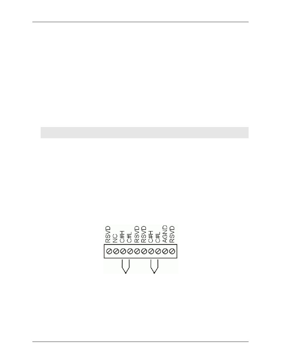
Connect the thermocouple to the WEB-TC using a differential configuration, as shown in Figure 3.
Figure 3. Typical thermocouple connection
Note
: There are two high/low channel pairs on each terminal. The # indicates the channel number. Do not
connect any signal or sensor to the pins labeled "NC" or "RSVD". These pins must remain disconnected for the
WEB-TC to operate according to specification.
Thermocouples must be connected to the WEB-TC such that they are floating with respect to AGND (pins 9,
19, 28, and 38). The WEB-TC AGND pins are isolated from earth ground, so connecting thermocouple sensors
to voltages referenced to earth ground is permissible as long as the isolation between the AGND pins and earth
ground is maintained.