Link/activity led, Digital logic voltage switch, Factory default reset button – Measurement Computing WEB-TC User Manual
Page 23
WEB-TC User's Guide
Functional Details
23
LINK/ACTIVITY LED
The
LINK/ACTIVITY
LED (lower LED) blinks green when a data packet is sent or received over the Ethernet
connection. The table below explains the function of the
LINK/ACTIVITY
LED.
LED
Indication
Blinking green
Data is being transmitted or received over the Ethernet connection.
Steady green
The Ethernet is idle.
Your network traffic has reached its maximum limit, and no communication is possible. Check with
your Network Administrator.
Off
The Ethernet cable is not connected to the WEB-TC.
The Ethernet cable is not connected to the network.
The Ethernet cable is damaged.
The Ethernet cable is not the correct type (a crossover cable is required for a direct connection.)
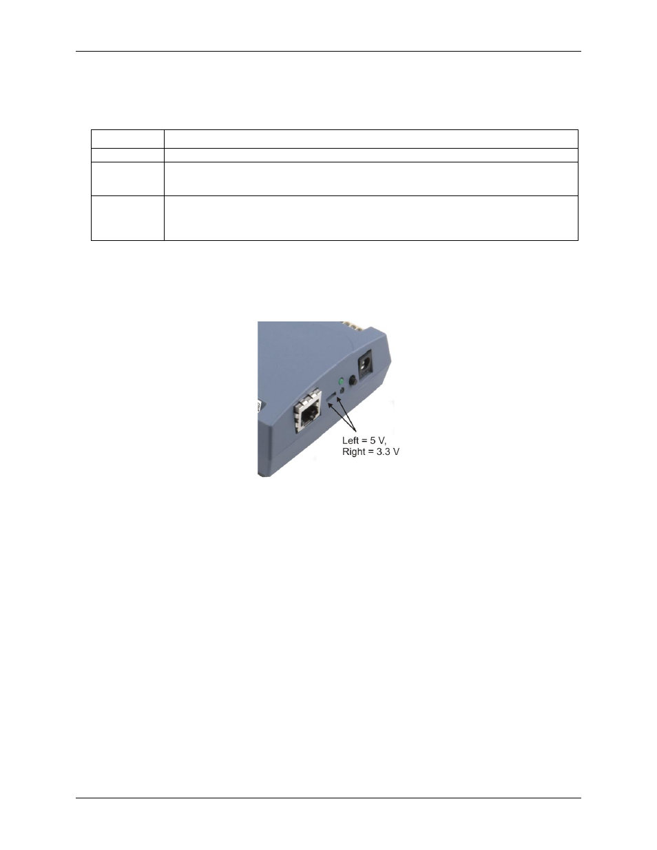
Digital logic voltage switch
The digital logic voltage switch lets you set the voltage to either 3.3 V or 5 V (default setting).
To interface with 3.3 V logic, use the 3.3 V setting. To interface with 5 V logic, use the 5 V setting. Refer to the
digital I/O specification on page 31 for the maximum and minimum threshold levels for each setting.
Figure 6. Output voltage switch positions
To change the logic voltage, slide the switch left or right with a screwdriver.
Factory default reset button
Press and hold this button for three seconds to restore the factory default network settings on the WEB-TC.
When held for 3 seconds, the
POWER
LED will turn off for a short time, indicating a reset is in process. When
the POWER LED turns back on, reset is complete and the factory default network settings have been restored.