Screw terminals, Ethernet port, External power connector – Measurement Computing WEB-TC User Manual
Page 22: Power/comm led
WEB-TC User's Guide
Functional Details
22
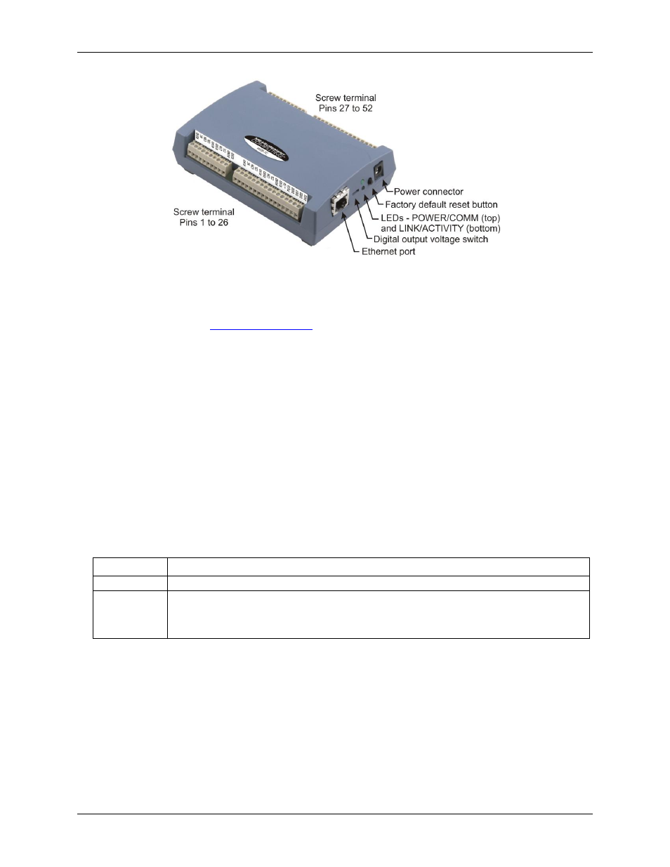
Figure 5. WEB-TC component locations
Screw terminals
The screw terminals provide connections for sensors, digital channels, power, and ground. Detailed information
is provided in Chapter 3,
, beginning on page 17.
Ethernet port
The WEB-TC has one 10BASE-T communication port. The port connector is an eight-position RJ-45
connector. Use the Ethernet cable provided to connect the device to a local or wide area network or to a hub
attached to a single computer. Use a CAT-5 (or higher) shielded or unshielded twisted pair crossover cable to
connect directly to a computer. The maximum communication distance without using a repeater is 100 meters.
Data can transmit up to 100 meters at speeds of up to 100 Mbps using only one crossover Ethernet cable
connected to your computer.
External power connector
Use the supplied external power supply (MCC p/n PS-5V2AEPS) to power the WEB-TC.
POWER/COMM LED
The
POWER/COMM
LED (upper LED) is steady green when external power is supplied. The WEB-TC has an
on-board voltage supervisory circuit that monitors the 5 V external power supply. The table below explains the
function of the
POWER/COMM
LED.
LED
Indication
Steady green
4.75 V to 5.25 V external power is supplied to the WEB-TC.
Off
Check the following:
External power is not supplied; verify that the supply is connected to the external power connector.
A power fault has occurred. A power fault occurs when the input power falls outside of the specified
voltage range of the external supply (4.75 V to 5.25 V).