External trigger, External clock, Counter – Measurement Computing USB-2627 User Manual
Page 23
USB-2627 User's Guide
Specifications
23
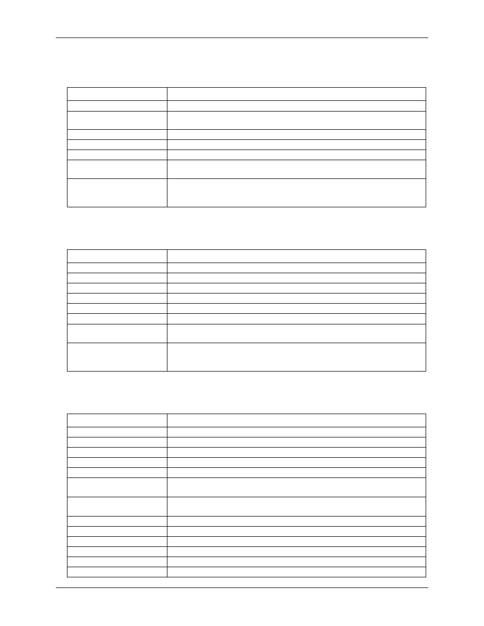
External trigger
Table 11. External trigger specifications
Parameter
Specification
Trigger source
TTLTRG
Trigger mode
Software programmable for edge or level sensitive, rising or falling edge, high or low
level. Power on default is edge sensitive, rising edge.
Trigger latency
1 µs + 1 clock cycle max
Trigger pulse width
100 ns min
Input type
33 Ω series resistor and 49.9 kΩ pull-down to GND
Input high voltage
2.2 V min
5.5 V absolute max
Input low voltage
1.5 V max
–0.5 V absolute min
0 V recommended min
External clock
Table 12. External clock I/O specifications
Parameter
Specification
Terminal names
XAPCR, XDPCR
Terminal types
Input, active on rising edge
Terminal descriptions
Receives pacer clock from external source
Input clock rate
1 MHz max
Clock pulse width
100 ns min
Input type
33 Ω series resistor, 47 kΩ pull-down to GND
Input high voltage
2.2 V min
5.5 V absolute max
Input low voltage
1.5 V max
–0.5 V absolute min
0 V recommended min
Counter
Table 13. Counter specifications
Parameter
Specification
Terminal names
CNT0, CNT1, CNT2, CNT3
Number of channels
4 channels
Resolution
32-bit
Counter type
Event counter
Input type
33 Ω series resistor, 47 kΩ pull-down to GND
Input source
68-pin SCSI:
CNT0 (pin 5), CNT1 (pin 39), CNT2 (pin 4), CNT3 (pin 38)
40-pin (J4):
CNT0 (pin 35), CNT1 (pin 34), CNT2 (pin 37), CNT3 (pin 36)
Counter read/writes rates
(software paced)
33 to 8,000 reads/writes per second typ; system dependent
Input high voltage
2.2 V min
Input low voltage
1.5 V max
Maximum input voltage range
–5 V to +10 V max
Input frequency
20 MHz, max
High pulse width
100 ns, min
Low pulse width
100 ns, min