Analog output, Output pacer clock, Digital i/o – Measurement Computing USB-2627 User Manual
Page 17: Pull-up/down configuration
USB-2627 User's Guide
Functional Details
17
Analog output
The USB-2627 has four 16-bit, 1 MHz analog output channels (
XDAC0
to
XDAC3
). The output range is fixed at
±10 V. All outputs can be updated at 1 MS/s, regardless of the number of channels in a scan.
Analog output connections are available on the SCSI connector and header connector J5.
Output pacer clock
You can pace the output waveform using the DAC scan clock on the board or with an external signal connected
to
XDPCR
.
The on-board programmable clock can generate updates ranging from 0.0149 Hz to 1 MHz.
Digital I/O
The USB-2627 has 24 TTL-level digital I/O lines that are configured as three 8-bit ports. Each bit is
configurable as either input or output. Digital I/O connections are available on the SCSI connector and header
connector J4.
You can read digital input ports asynchronously before, during, or after an analog input scan. Digital outputs
can be updated asynchronously before, during, or after an acquisition.
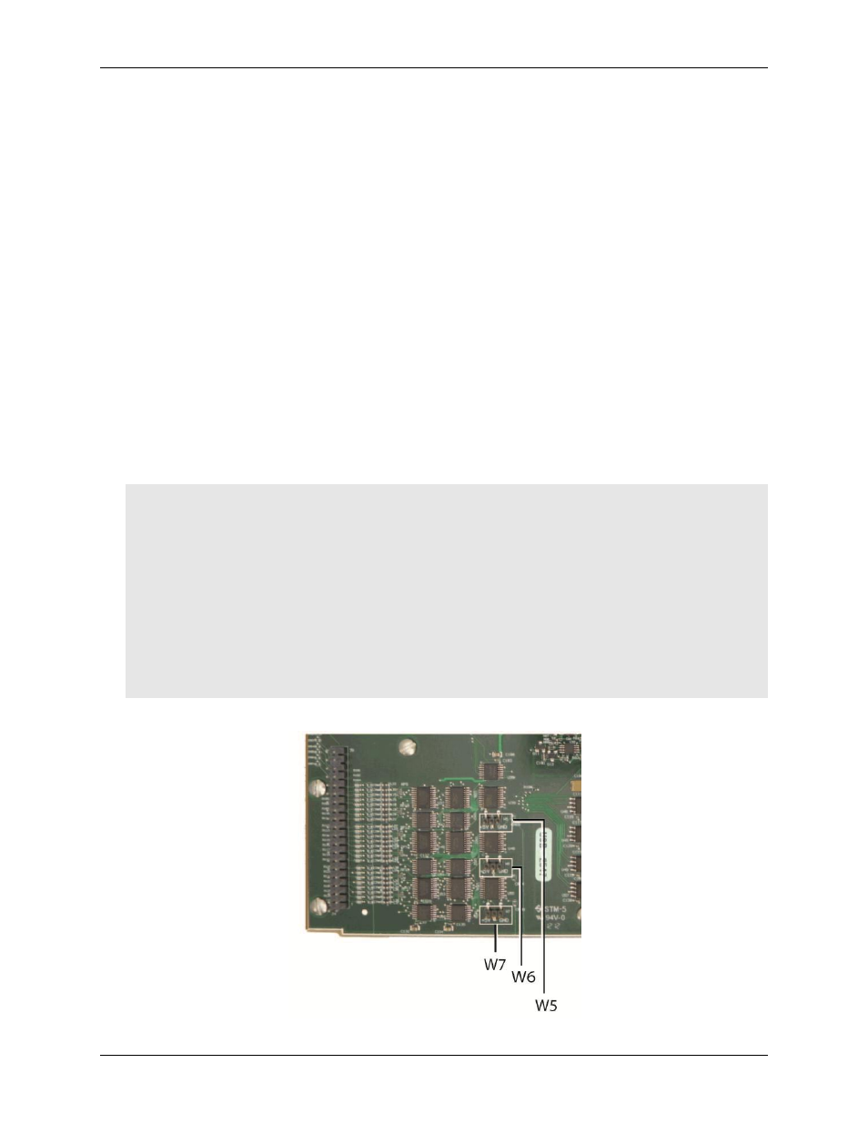
Pull-up/down configuration
Each digital port has 47 kΩ resistors that are jumper configurable as pull-up or pull-down (default). Jumper
W7
configures Port A,
W6
configures Port B, and
W5
configures Port C.
Caution! Turn off power to all devices connected to the system before making connections. Electrical shock
or damage to equipment can result even under low-voltage conditions.
Always handle components carefully, and never touch connector pins or circuit components unless
you are following ESD guidelines in an appropriate ESD-controlled area. These guidelines include
using properly-grounded mats and wrist straps, ESD bags and cartons, and related procedures.
Avoid touching board surfaces and onboard components. Only handle boards by their edges. Make
sure that the USB-2627 does not come into contact with foreign elements such as oils, water, and
industrial particulate.
The discharge of static electricity can damage some electronic components. Semiconductor
devices are especially susceptible to ESD damage.
Figure 9 shows the location of each jumper on the board.
Figure 9. Pull-up/down jumper locations