Pin header connectors j2, j4, and j5, Usb connector, Leds – Measurement Computing USB-2627 User Manual
Page 16: Standoffs, Signal descriptions, Analog input, Input pacer clock, Channel-gain queue
USB-2627 User's Guide
Functional Details
16
40-pin header connectors J2, J4, and J5
The header connectors provide alternative connections to the SCSI connector.
J2
provides connections for the analog inputs.
J4
provides connections for the DIO, counter inputs, timer outputs, input scan clock, and power output.
J5
provides connections for the analog outputs, timer outputs, I/O scan clocks, and power output.
Refer to Figure 4 and Figure 5 on page 12 for header connector pinouts.
USB connector
The USB connector provides +5 V power and communication. No external power supply is required.
LEDs
The USB-2627 has two LEDs –
Power
and
Activity
.
The
Power
LED (top) turns on when the device is detected and installed on the computer.
The
Activity
LED (bottom) blinks when data is transferred, and is off otherwise.
Standoffs
The board is shipped with standoffs that can be used for mounting onto a metal frame.
Signal descriptions
Analog input
The USB-2627 has a 16-bit A/D converter and provides 16 single-ended analog inputs. The input voltage range
is fixed at ±10 V. Analog input connections are available on the SCSI connector and on header connector J2:
SCSI connector P1 provides connections for
ACH0
to
ACH15
Header connector J2 provides connections for
ACH0
to
ACH15
Input pacer clock
You can pace input scanning operations using the input scan clock on the board or with an external signal
connected to
XAPCR
. The sampling rate is software-selectable for 0.0149 Hz to 1 MHz.
Channel-Gain queue
The USB-2627 channel-gain queue feature allows you to configure a list of channels to scan. The settings are
stored in a channel-gain queue list that is written to local memory on the device.
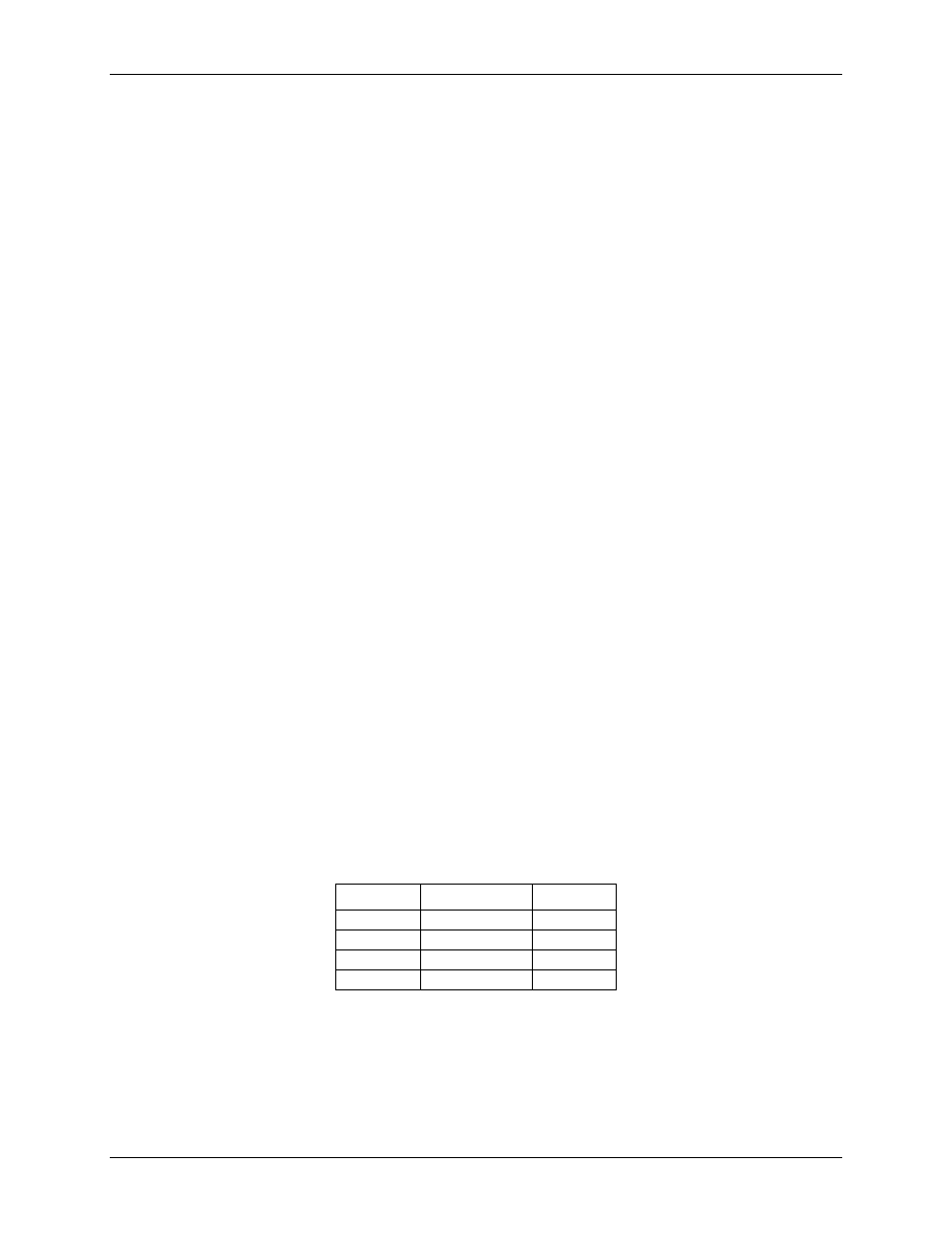
The channel-gain queue list can contain up to 16 elements. The channels can be listed in any order. An example
of a 4-element list is shown in the table below.
Sample channel-gain queue list
Element
Channel
Range
0
CH5
BIP10V
1
CH3
BIP10V
2
CH5
BIP10V
3
CH15
BIP10V