Counter input, Trigger input, Timer output – Measurement Computing USB-2627 User Manual
Page 18: Ground
USB-2627 User's Guide
Functional Details
18
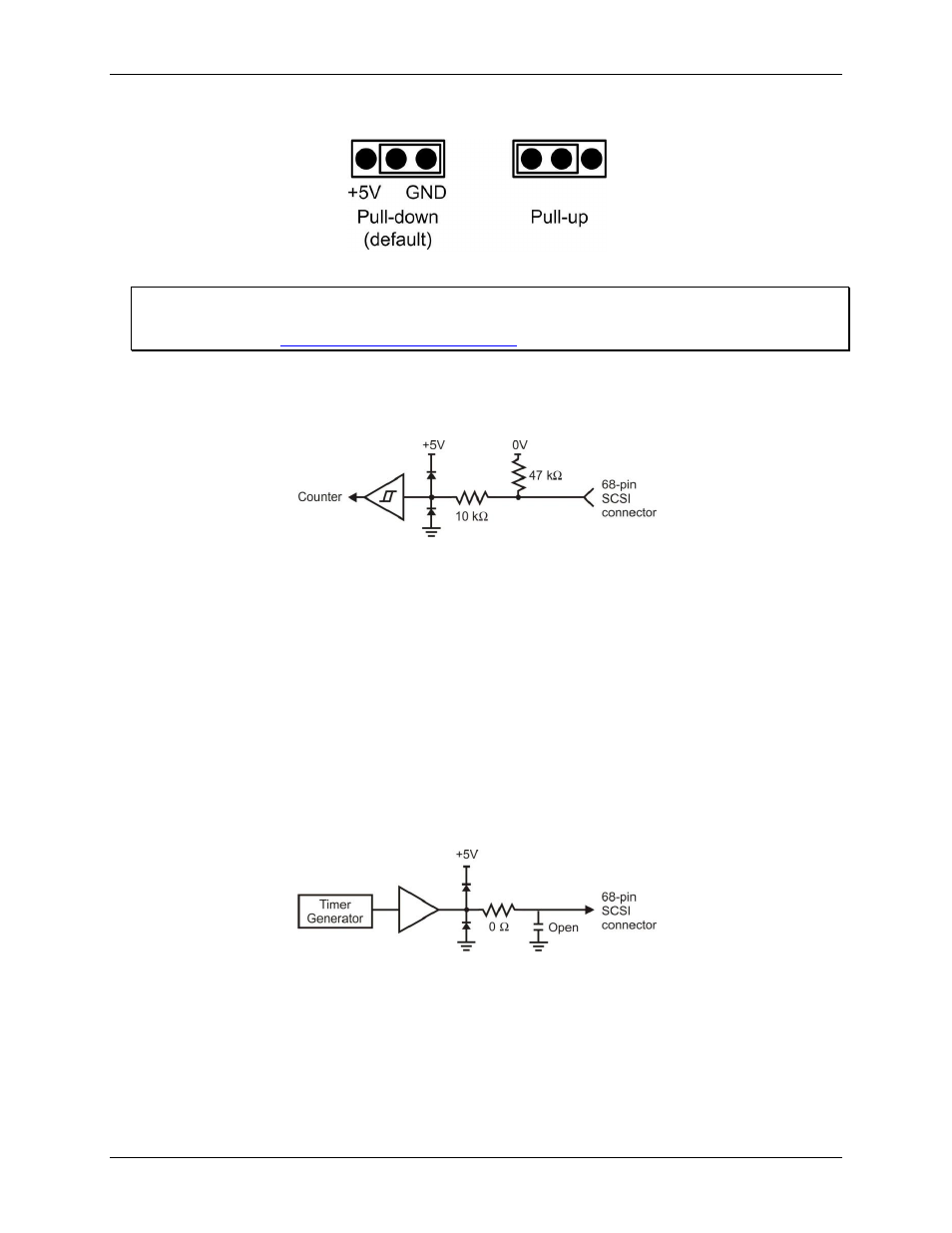
Figure 10 shows the pull-up and pull-down configuration for each jumper.
Figure 10. Pull-up/down jumper configurations
For more information about digital signal connections
For general information about digital signal connections and digital I/O techniques, refer to the Guide to DAQ
Signal Connections
Counter input
The four counter inputs (
CNT0
to
CNT3
) are 32-bit event counters that can accept frequency inputs up to
20 MHz.
Figure 11. Typical counter input
Counter input connections are available on the SCSI connector and header connector J4.
Trigger input
The external digital trigger input (
TTLTRIG)
is software selectable for edge or level sensitive.
Edge sensitive mode is configurable for rising or falling edge.
Level sensitive mode is configurable for high or low level.
The default setting at power up is edge sensitive, rising edge. The trigger input connection is available on the
SCSI connector and header connectors J4 and J5.
Timer output
The four timer outputs (
TMR0
to
TMR3
) are pulse width modulation (PWM) outputs that can generate a square
wave with a programmable frequency in the range of 0.015 Hz to 32 MHz. Figure 12 shows the timer output
schematic.
Figure 12. Typical timer output
Timer output connections are available on the SCSI connector and header connectors J4 and J5. TMR0 and
TMR1 are available on the SCSI connector and header connector J4. TMR2 and TMR3 are available on header
connector J5.
Ground
The analog ground (
AGND
) pins provide a common ground for all analog channels. The digital ground (
GND
)
pins provide a common ground for the digital, counter, timer, and clock channels and the power terminal.