Cabling, Signal termination – Measurement Computing USB-2627 User Manual
Page 13
USB-2627 User's Guide
Signal Connections
13
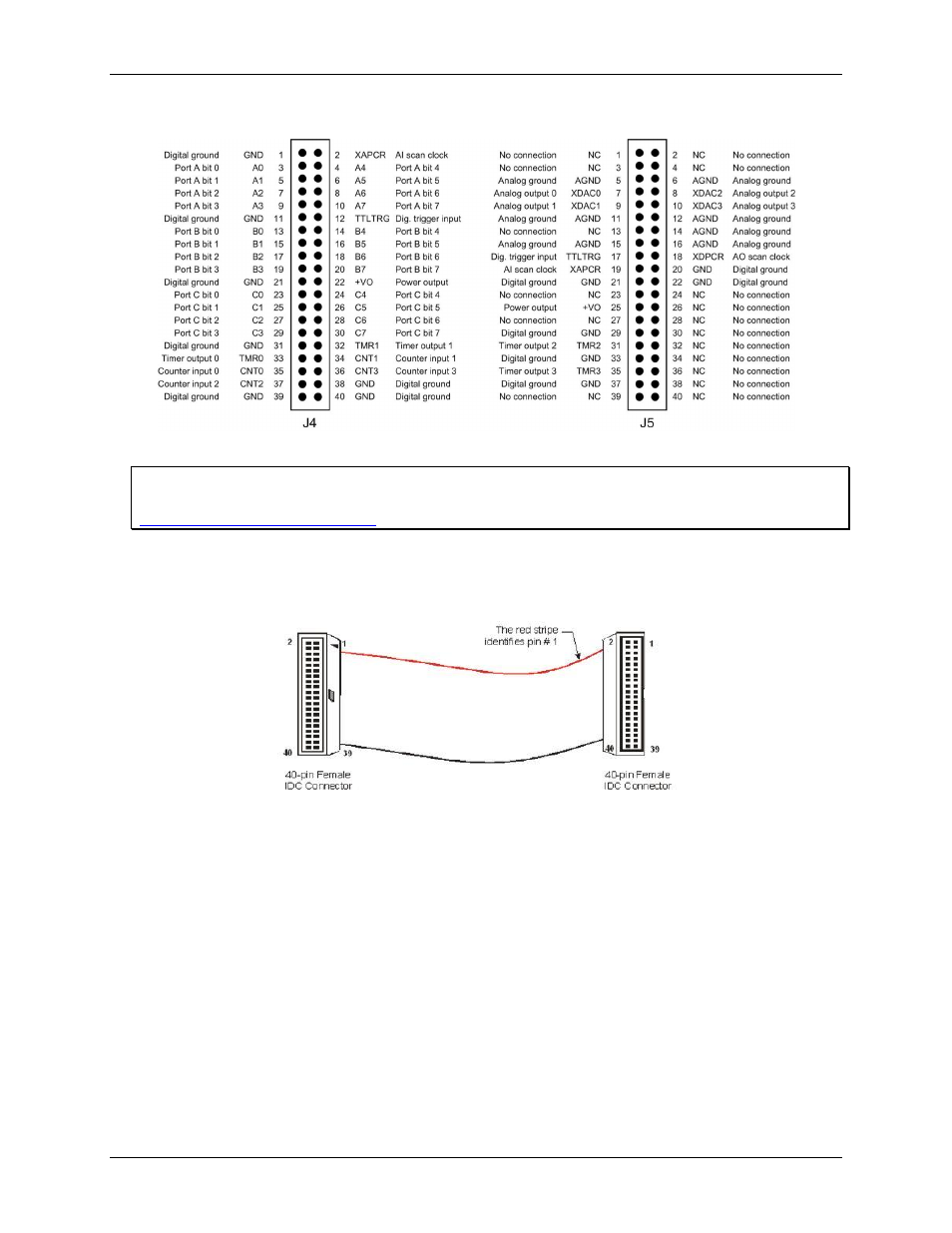
Figure 5 shows the pinout for J4 and J5.
Figure 5. Header connector J4 and J5 pinout
For more information about signal connections
For more information about analog input connections, refer to the Guide to DAQ Signal Connections at
Cabling
Use a C40FF-x cable (Figure 6) when connecting signals to a 40-pin header connector.
Figure 6. C40FF-x cable
Connecting a C40FF-x cable to each 40-pin connector provides greater signal connectivity than what is
provided by the SCSI connector.
Signal termination
CIO-MINI40
– 40-pin screw terminal board that connects to the J2, J4, or J5 header connector with the
C40FF-x cable.
TB-103
– screw terminal board that mounts directly onto the header connectors.