Pin header connectors j2, j4, and j5 – Measurement Computing USB-2627 User Manual
Page 12
USB-2627 User's Guide
Signal Connections
12
TB2 terminal
SCSI pin
TB1 terminal
SCSI pin
CNT3
38
XDAC1
21
TMR0
3
AGND
AGND
TMR1
37
XAPCR
2
XDPCR
1
GND
GND
GND
GND
EGND
SCSI shell
Do not make connections to any terminal labeled NC.
Note 1: Labeled POSREF on the TB-100; not supported on the USB-2627.
Note 2: Labeled NEGREF on the TB-100; not supported on the USB-2627.
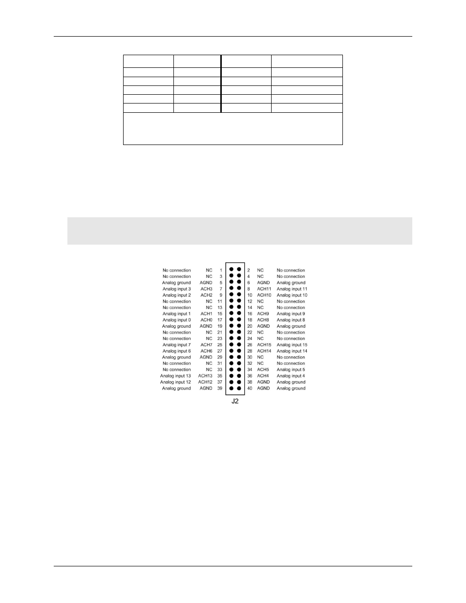
40-pin header connectors J2, J4, and J5
The header connectors provide alternative connections to the 68-pin connector. Pins 1, 2, 39, and 40 are labeled
on each connector.
J2
provides analog input connections.
J4
provides digital, counter, timer, pacer input, and power output
connections.
J5
provides analog output, timer, pacer I/O, and power output connections.
Caution!
Avoid redundant connections!
Make sure there is no signal conflict between the SCSI connector
pins and header connector pins. Failure to do so could possibly cause equipment damage and/or
personal injury.
Figure 4 shows the pinout for J2.
Figure 4. Header connector J2 pinout