Usb-2627 components, Pin scsi connector p1 – Measurement Computing USB-2627 User Manual
Page 15
USB-2627 User's Guide
Functional Details
15
USB-2627 components
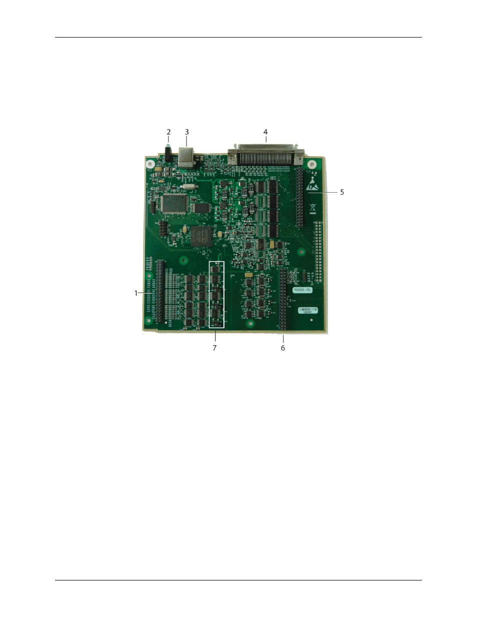
These USB-2627 components are shown in Figure 8.
68-pin SCSI connector (P1)
40-pin header connectors (J2, J4, and J5)
USB connector
LED indicators (USB and Power)
1
40-pin connector J4
5
40-pin connector J2
2
LEDs
6
40-pin connector J5
3
USB connector
7
Pull-up/down jumpers (W5. W6, W7)
4
68-pin SCSI connector P1
Figure 8. USB-2627 components
68-pin SCSI connector P1
The 68-pin SCSI connector provides the following connections:
16 single-ended analog inputs (ACH0 to ACH15)
Four analog outputs (XDAC0 to XDAC3)
24 digital I/O (A0 to A7, B0 to B7, C0 to C7)
Four counter inputs (CNT0 to CNT3)
Two timer outputs (TMR0 to TMR1)
External AI scan clock input (XAPCR)
External AO scan clock input (XDPCR)
External digital trigger input (TTLTRG)
Power output (+VO)
Analog ground and digital ground (AGND and GND)
Refer to Figure 2 on page 10 for the SCSI connector pinout.