A/d converter range (s2 switch), Trigger edge (p8 jumper) – Measurement Computing PCIe-DAS1602/16 User Manual
Page 9
PCIe-DAS1602/16 User's Guide
Installing the PCIe-DAS1602/16
9
A/D converter range (S2 switch)
Use the S2switch to set the A/D converter range. This switch controls all A/D channels.
Switch S2 is factory-configured for bipolar. To configure for unipolar, set this switch to UNI.
Figure 4. A/D range select switch (S2)
Trigger edge (P8 jumper)
Use the P8 jumper to set the A/D pacer clock trigger edge. This jumper selects the edge that initiates the A/D
conversion when using the internal pacer clock.
Jumper P8 is factory-configured for rising edge.
When using the falling edge to start the conversion, the A/D may be falsely triggered by glitches in the 8254
pacer clock initialization. If the PCIe-DAS1602/16 is replacing an older series MCC board, using the rising
edge to start the conversion may lead to timing differences.
For compatibility with MCC software and third-party packages, leave jumper P8 in the default rising edge
position.
Figure 5 and Figure 6 show the edge selection options for jumper P8.
Figure 5. Jumper P8 set for rising edge
Figure 6. Jumper P8 set for falling edge
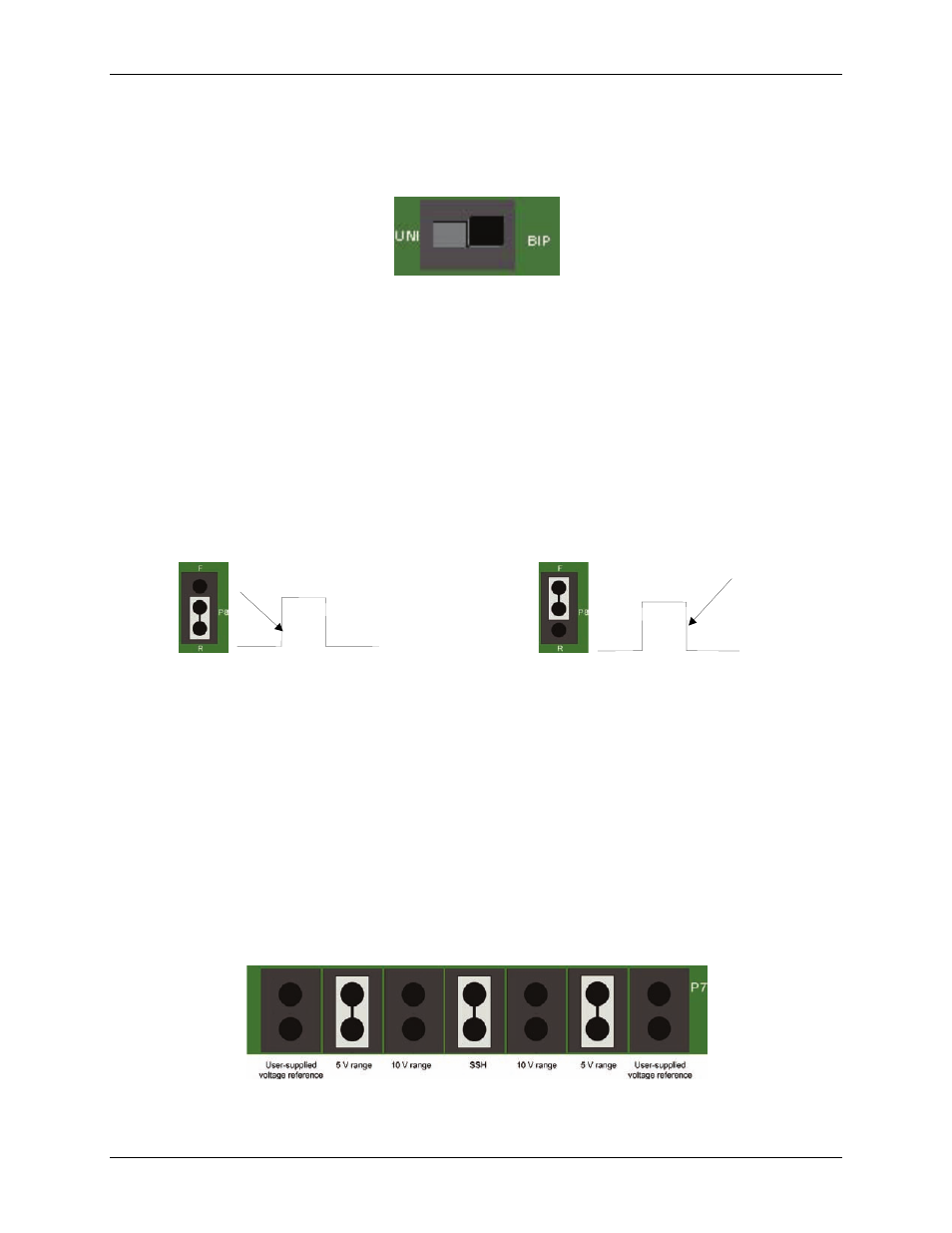
D/A converter (DAC) output range (P5, P6, and P7 jumpers)
Use the P7 jumpers to set the PCIe-DAS1602/16 onboard precision voltage reference and select the output
ranges of the DACs. Both DACs are factory-configured for a range of –5 V to +5 V (Figure 7.)
Two 12-bit multiplying DACs (DAC0 and DAC1) provide analog output. These DACs accept an input
reference voltage, and provide an output voltage which is both inverse to the reference voltage and proportional
to the digital value in the output register. The proportion is controlled by the D/A output code (0 to 4095). Each
bit represents 1/4096 of full scale (FS). For example, in unipolar mode, the supplied reference of 5 V provides a
+5 V output (actually 4.9988 V) when the value in the output register is 4095 (FS at 12 bits of resolution). It
provides a value of 2.5 V when the value in the output register is 2048.
A precision 5 V and 10 V reference provides onboard D/A ranges of 0 V to 5 V, 0 V to 10 V, ±5 V, ±10 V.
Other ranges between 0 V and 10 V are available when you provide a precision voltage reference at pin
10 (DAC0 REF IN) or pin 26 (DAC1 REF IN) of the main connector.
Figure 7. DAC0 and DAC1 range jumpers (P7)