Simultaneous sample and hold (ssh) trigger, Clock select (p2 jumper), Pull-up/down configuration (p3 jumpers) – Measurement Computing PCIe-DAS1602/16 User Manual
Page 10
PCIe-DAS1602/16 User's Guide
Installing the PCIe-DAS1602/16
10
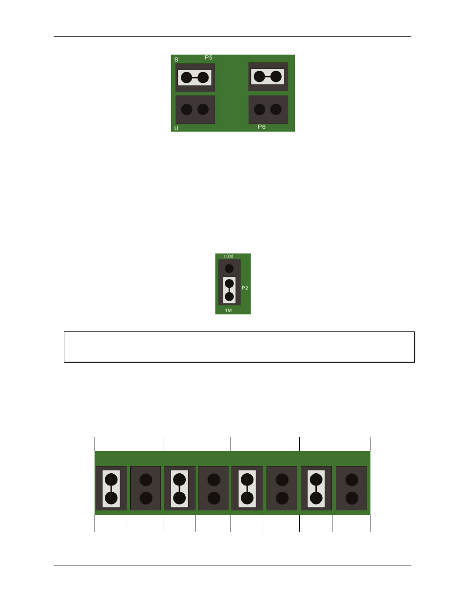
Figure 8. DAC0 (P5) and DAC1 (P6) unipolar/bipolar jumpers
Simultaneous sample and hold (SSH) trigger
When the DAC1 reference is supplied onboard, pin 26 on the 37-pin connector is unused (Figure 11). You can
enable this pin as a SSH trigger for use with the CIO-SSH16 board. To enable SSH, place the jumper between
the two pins labeled SSH in Figure 7.
Clock select (P2 jumper)
Use the P2 jumper to configure the frequency of the square wave used as a clock by the A/D pacer circuitry.
This pacer circuitry controls the sample timing of the A/D.
The clock select jumper is factory-configured for 1 MHz, as shown in Figure 9. You can set the clock source to
10 MHz if needed for the sample rates you plan to use.
Figure 9. Clock select (P2)
Internal pacer output is also available at pin 20
The internal pacer output driving the A/D converter is also available at pin 20 (CTR 3 Output) on the main I/O
connector (see Figure 11 on page 12).
Pull-up/down configuration (P3 jumpers)
Use the P3 jumpers to set the digital bits for pull-up (+5 V) or pull down (0 V) when the PCIe-DAS1602/16 is
powered on and reset. Ports A, B, CH, and CL are factory configured for pull-up.
These jumpers establish either a high (pull-up) or low (pull-down) logic level at each of the eight DIO lines on
ports A and B, and at each of the four DIO lines on ports CL and CH. The default pull-up configuration for all
ports is shown in Figure 10.
Port A
Port B
Port CL
Port CH
P3
Pull-up
Pull-down
Pull-up Pull-down Pull-up
Pull-down
Pull-up
Pull-down
Figure 10. Pull-up/pull-down jumpers (P3)