Analog connector, Digital connector, D (figure 11) – Measurement Computing PCIe-DAS1602/16 User Manual
Page 12
PCIe-DAS1602/16 User's Guide
Installing the PCIe-DAS1602/16
12
Connectors, cables, and accessories
Description
Compatible accessory products
(with the C37FF-x cable or C37FFs-x cable)
CIO-MINI37
SCB-37
ISO-RACK16
ISO-DA02
Compatible accessory products
(with the C37FF-x cable or C37FFs-x cable
connected to the BP40-37 cable)
CIO-ERB08
CIO-ERB24
SSR-RACK08
SSR-RACK24
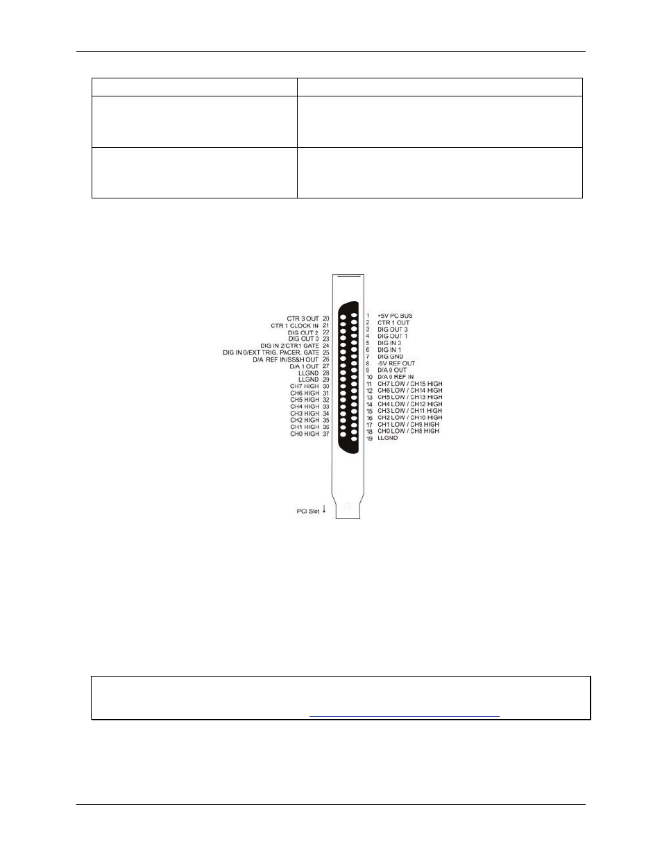
Analog connector
The PCIe-DAS1602/16 board's analog connector is a 37-pin "D" connector that is accessible from the rear of
the computer on the expansion back plate. This connector accepts female 37-pin D-type connectors, such as the
C37FF-x 37-pin cable (Figure 14) or the C37FFS-x 37-pin shielded cable (Figure 15).
Figure 11. Main I/O connector pin out
An additional signal, Simultaneous Sample and Hold Output (SS&H OUT), is available at pin 26 of the analog
connector. This pin is required when the CIO-SSH16 board is used with a PCIe-DAS1602/16. Refer to
Simultaneous sample and hold (SSH) trigger for information on how to configure this pin.
Digital connector
The PCIe-DAS1602/16 digital I/O connector is a 40-pin connector that is mounted at the rear of the PCIe-
DAS1602/16. This connector accepts a 40-pin header connector (Figure 16).
The optional BP40-37 cable assembly brings the signals to a back plate with a 37-pin male connector mounted
in it.
Analog and digital connections and configuration
General information on analog and digital signal connections and configuration is contained in the Guide to
Signal Connections (available on our web sit