Accuracy, Analog output drift, Digital input/output – Measurement Computing PCIe-DAS1602/16 User Manual
Page 19: Digital i/o connector, Main connector
PCIe-DAS1602/16 User's Guide
Specifications
19
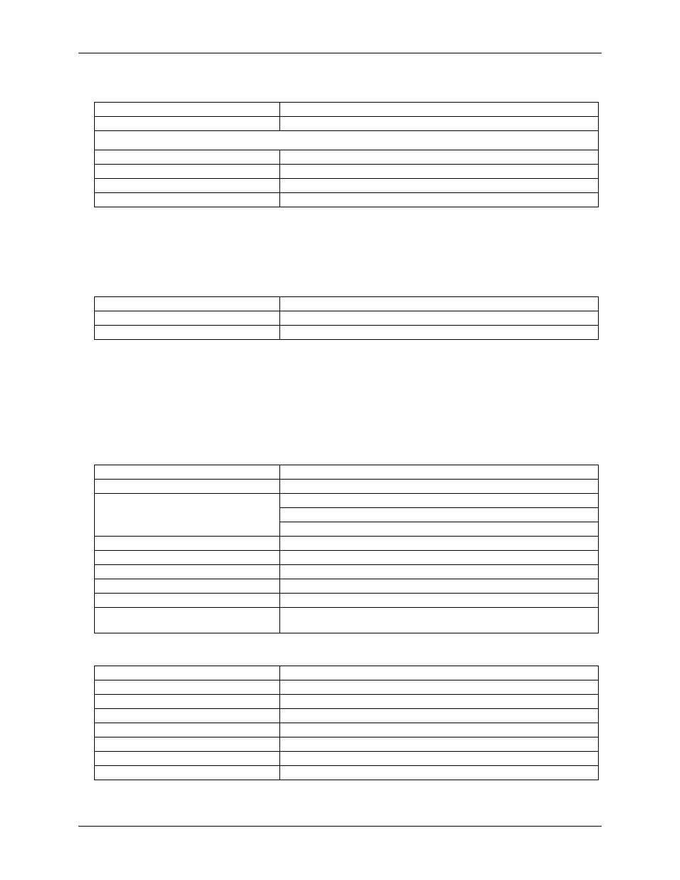
Accuracy
Typical accuracy
±1 LSB
Absolute accuracy
±2 LSB
Accuracy Components
Gain error
Trimmable by potentiometer to 0
Offset error
Trimmable by potentiometer to 0
Integral linearity error
±0.5 LSB typ, ±1 LSB max
Differential linearity error
±0.5 LSB typ, ±1 LSB max
Total board error is a combination of gain, offset, differential linearity and integral linearity error. The
theoretical absolute accuracy of the board may be calculated by summing these component errors. Worst case
error is realized only in the unlikely event that each of the component errors is at their maximum level, and
causes error in the same direction.
Analog output drift
Analog output FS gain drift
±0.22 LSB/°C max
Analog output zero drift
±0.22 LSB/°C max
Overall analog output drift
±0.44 LSB/°C max
Absolute error change per °C temperature change is a combination of the gain and offset drift of many
components. The theoretical worst case error of the board may be calculated by summing these component
errors. Worst case error is realized only in the unlikely event that each of the component errors is at their
maximum level, and causing error in the same direction.
Digital input/output
Digital I/O connector
Digital type
82C55
Number of I/O
24
Configuration per 82C55
2 banks of 8 and 2 banks of 4 or
3 banks of 8 or
2 banks of 8 with handshake
Input high
2.0 V min, 5.5 V absolute max
Input low
0.8 V max, –0.5 V absolute min
Output high
3.0 V min @ –2.5 mA
Output low
0.4 V max @ 2.5 mA
Power-up/reset state
Input mode (high impedance)
Pull-up/pull-down resistors
All pins pulled up to +5
V via individual 47 kΩ resistors, by default.
Selectable at jumper P8
Main connector
Digital output type
74ACT244, power up/reset to LOW logic level
Digital input type
74AHCT373, pulled to logic high via 47 K resistors
Number of I/O
8
Configuration
4 fixed input, 4 fixed output
Output high
2.7 V @ –0.4 mA min
Output low
0.5 V @ 8 mA max
Input high
2.0 V min, 7 V absolute max
Input low
0.8 V max, –0.5 V absolute min