7 pacer clock control register – Measurement Computing PC104-DAS16JR/12 User Manual
Page 21
3.7 PACER CLOCK CONTROL REGISTER
BASE ADDRESS + 10
TRIG0
CTR0
X
X
X
X
X
X
0
1
2
3
4
5
6
7
WRITE only
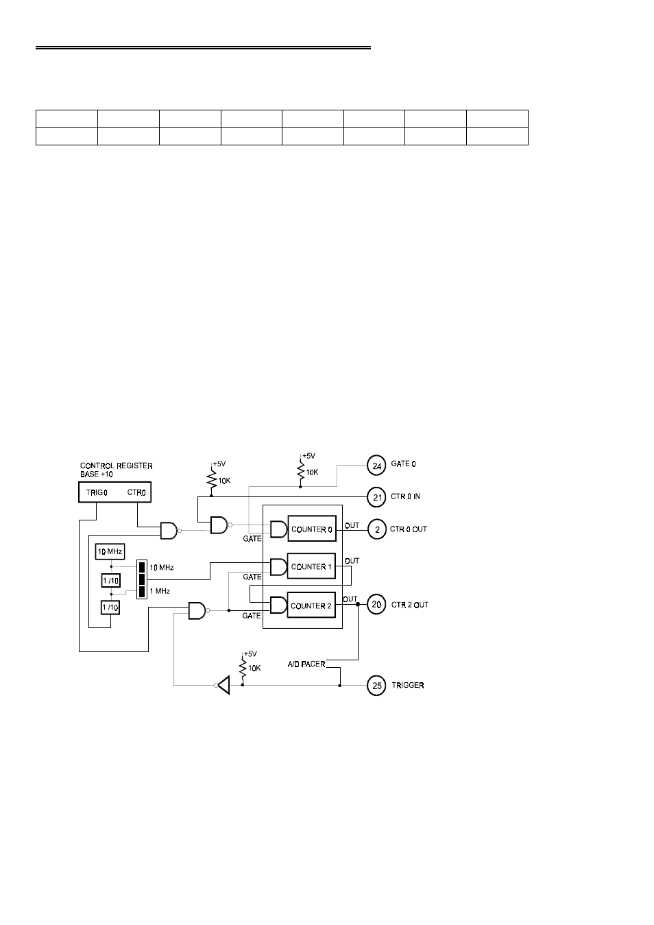
CTR0 = 1. When CTR0 = 1, an on-board 100 kHz clock signal is ANDed with
the COUNTER 0 CLOCK INPUT (pin 21). A high on pin 21 will allow pulses
from the on-board source into the 8254 Counter 0 input.
CTR0 = 0. When CTR0 = 0, the input to 8254 Counter 0 is entirely dependent on
pulses at pin 21, COUNTER 0 CLOCK INPUT.
TRIG0 = 1. When TRIG0 = 1, the TRIGGER input at pin 25 is ANDed with
TRIG0 which must be high for the pulses from the on-board pacer clock (8254)
to start A/D conversions. The input at pin 25 is pulled up and will always be high
unless pulled low externally.
TRIG0 = 0. When = 0, the GATEs of counter 1 & 2 are held high, preventing the
gating of the pacer externally from pin 25.
Figure 3-1 shows the relationship of this register to the pacer counters and associated
logic..
Figure 3-1. Pacing Control Counters
17