3 register architecture, 1 control & data registers – Measurement Computing PC104-DAS16JR/12 User Manual
Page 15
3 REGISTER ARCHITECTURE
3.1 CONTROL & DATA REGISTERS
The PC104-DAS16Jr/xx is controlled and monitored by writing to and reading from
16 consecutive 8-bit I/O addresses. The first address, or BASE ADDRESS, is
determined by setting a bank of switches on the board.
Most often, register manipulation is best left to experienced programmers with a
specific need for low level control. If this is the case for you, use the information that
follows to write your own code. Otherwise, we strongly suggest you consider using
the Universal Library™ instead.
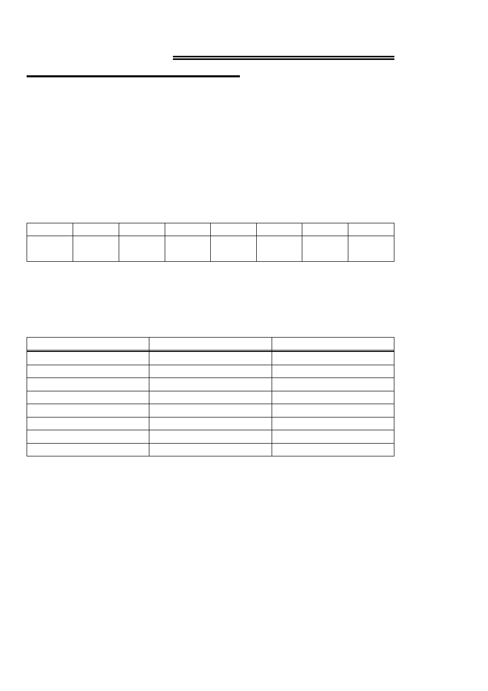
The register descriptions all follow the format:
CH1
CH2
CH4
CH8
A/D12
LSB
A/D11
A/D10
A/D9
0
1
2
3
4
5
6
7
The numbers along the top row are the bit positions within the 8-bit byte and the
numbers and symbols in the bottom row are the functions associated with that bit.
To write to or read from a register in decimal or HEX, the following weights apply:
Table 3-1. Bit Weights
80
128
7
40
64
6
20
32
5
10
16
4
8
8
3
4
4
2
2
2
1
1
1
0
HEX VALUE
DECIMAL VALUE
BIT POSITION
To write control or data to a register, the individual bits must be set to 0 or 1 then
combined to form a Byte.
The method of programming required to set/read bits from bytes is beyond the scope
of this manual.
In summary form, the registers and their function are listed on Table 3-2.
11