Measurement Computing PC104-DAS16JR/12 User Manual
Page 14
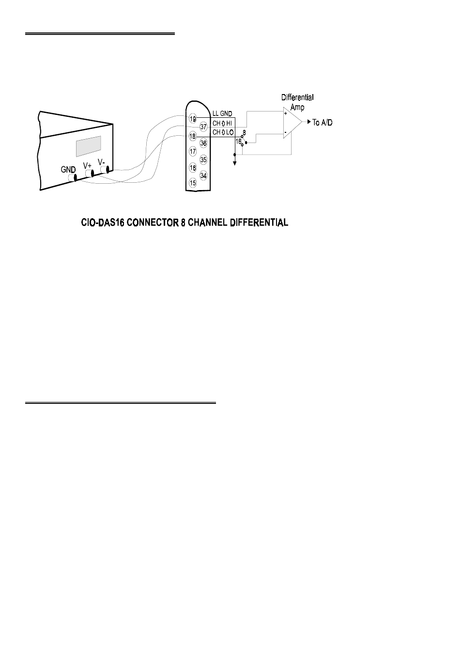
2.5 DIFFERENTIAL INPUT
A differential signal has three wires from the signal source. The signals are Signal
Figure 2-6. Differential Connections
High (CH# HIGH), Signal Low (CH# LOW) and Signal Ground (LLGND). See
Figure 2-6.
A differential connection allows you to connect the board to a signal source with a
ground that is different than the PC ground, but less than 10V difference, and still
make a valid measurement of the signal between CH# HIGH and CH# LOW.
EXAMPLE:
A laboratory instrument with its own wall plug. There are sometimes differences in
wall GND between outlets.
2.6 DIGITAL OUTPUTS & INPUTS
All the digital outputs inputs are TTL level. TTL is an electronics industry term, short
for Transistor Transistor Logic, with describes a standard for digital signals which are
either at 0V or 5V (nominal). The binary logic inside the PC is all TTL or LSTTL
(Low power Schotky TTL). Both specifications are presented here.
10