4 4-bit digital i/o registers – Measurement Computing PC104-DAS16JR/12 User Manual
Page 18
WRITE
The channel scan limits desired are written as one byte. The high channel number
scan limit is in the most significant 4 bits. The low channel scan limit is in the
least significant 4 bits.
Bits 3-0 contain the starting channel number and bits 7-4 contain the ending channel
number. If you wanted to scan channels 1, 2, 3 in that order, do so by placing the 3 in
bits 7-4 and the 1 in bits 3-0.
NOTE
Every write to this register sets the current A/D channel MUX
setting to the number in bits 0-3. See BASE + 8.
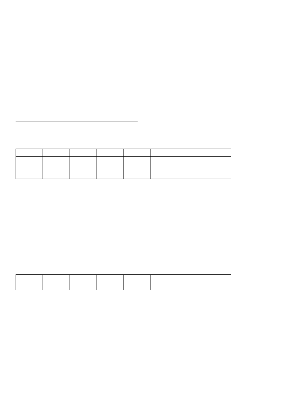
3.4 4-BIT DIGITAL I/O REGISTERS
BASE ADDRESS + 3
DI0,
TRIG
DI1
DI2,
CTR 0
GATE
DI3
0
0
0
0
0
1
2
3
4
5
6
7
When read...
READ
The signals present at the inputs are read as one byte, the most significant 4 bits of
which are always zero. The pins 25 (digital input 0) and 24 (digital input 2) digital
inputs have two functions each.
The TRIG function of digital input 0 may be used to hold of the first sample of an
A/D set by holding it low (0V) until you are ready to take samples, which are then
paced by the 8254. It can also be used as the source of an external start conversion
pulse, synchronizing A/D conversions to some external event.
When written to..
DO0
DO1
DO2
DO3
X
X
X
X
0
1
2
3
4
5
6
7
WRITE
The upper four bits are ignored. The lower four bits are latched TTL outputs.
Once written, the state of the inputs cannot be read back because a read back
would read the separate digital input lines (see above).
14