2 analog inputs – Measurement Computing PC104-DAS16JR/12 User Manual
Page 11
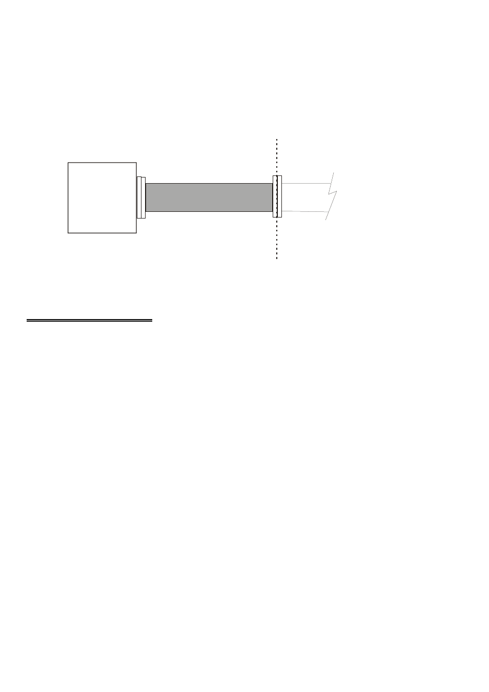
The BP40-37 Adapter connector accepts female 37-pin, D-type connectors, such as
those on the C37FF-2, 2 foot cable with connectors (Figure 2-3). If frequent changes
to signal connections or signal conditioning is required, please refer to the information
on the CIO-MINI37, CIO-TERMINAL screw terminal board, CIO-EXP32, 32
channels analog MUX/AMP, CIO-SSH16, 16 channel simultaneous sample & hold
board or the ISO-RACK16 5B module interface rack.
Figure 2-3. Cabling Using a BP40-37
2.2 ANALOG INPUTS
Analog inputs may be connected in three different configurations. These are Single
Ended, Floating Differential and Differential.
WARNING - PLEASE READ
Measure the voltage between the ground signal at the signal source
and the PC. If there is more than 10 volts, do not connect the board
because you will not be able to make any reading. If the voltage is
more than 30 volts, DO NOT connect to this signal because it will
damage the board and possibly the computer.
7
P C 1 0 4 -D A S 1 6 JR /x x
3 7 -p in c a b le , a s
C 3 7 F F -x, e tc.
B a c k P la te
B P 4 0 -3 7