Measurement Computing DAQFlex User Manual
Page 43
DAQFlex Message-based Firmware Specification
Hardware Reference – USB-7204
43
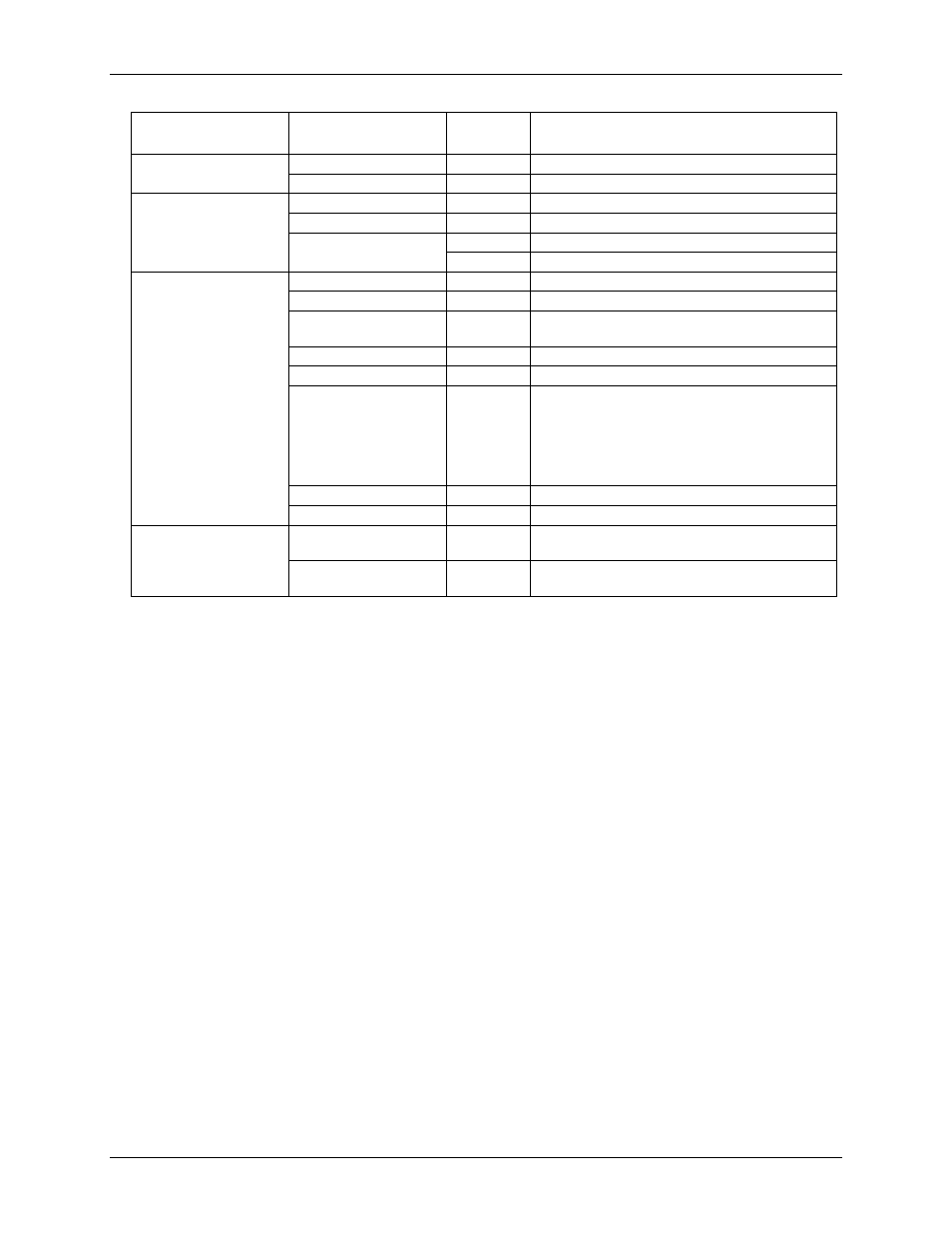
Component
Supported
Property/Command
Set/Get
Supported Values
STOP
TRIG
Set/Get
ENABLE, DISABLE
CTR
START
STOP
VALUE
Set
0
Get
0 to 4,294,967,295
DEV
DATATYPE
Set/Get
ENABLE, DISABLE
FLASHLED/{n}
Set
0 to 255
FWV
Get
MM.mm (M = major;
m = minor)
ID
Set/Get
Up to 56 characters
MFGCAL
Get
yyyy-mm-dd HH:MM:SS
MFGCAL{item}
Get
YEAR as yyyy; 20xx
MONTH as mm; 01 to 12
DAY as dd; 01 to 31
HOUR as HH; 01 to 23
MINUTE as MM; 01 to 59
SECOND as SS; 01 to 59
MFGSER
Get
Up to 8 hexadecimal digits
RESET/{value}
DEFAULT, SYSTEM
DIO
DIR
Set/Get
IN, OUT
(port-configurable)
VALUE
Get
0 to 255 (port)
0 to 1 (bit)
Hardware features
8 analog input channels, numbered 0-7.
Analog input mode is configurable for single-ended (8 channels) or differential (4 channels).
Gain ranges:
o ±20V (differential mode)
o ±10V (differential or single–ended mode)
o ±5V (differential mode)
o ±4V (differential mode)
o ±2.5V (differential mode)
o ±2V (differential mode)
o ±1.25V (differential mode)
o ±1V (differential mode)
2 analog output channels, numbered 0 to 1.
Analog output range is 0 to 4.096 V, 1 mV per LSB
2 digital ports. Each port is individually configurable as input or output.
External trigger input
External pacer input/output
This feature allows multiple devices to acquire synchronized samples. One master device is used to
drive the signal. Additional devices must be configured as slave devices using the
"AISCAN:EXTPACER=value" message. Value may be "ENABLE/MASTER," "ENABLE/SLAVE," or
"ENABLE/GSLAVE."
o When set to ENABLE/SLAVE, the first clock pulse after setting up the scan is ignored to ensure
adequate setup time for the first conversion. Use this mode when the device is paced from a
continuous clock source.