Measurement Computing DAQFlex User Manual
Page 22
DAQFlex Message-based Firmware SpecificationHardware Reference – USB-204, USB-201, USB-204-OEM, and USB-201-OEM
22
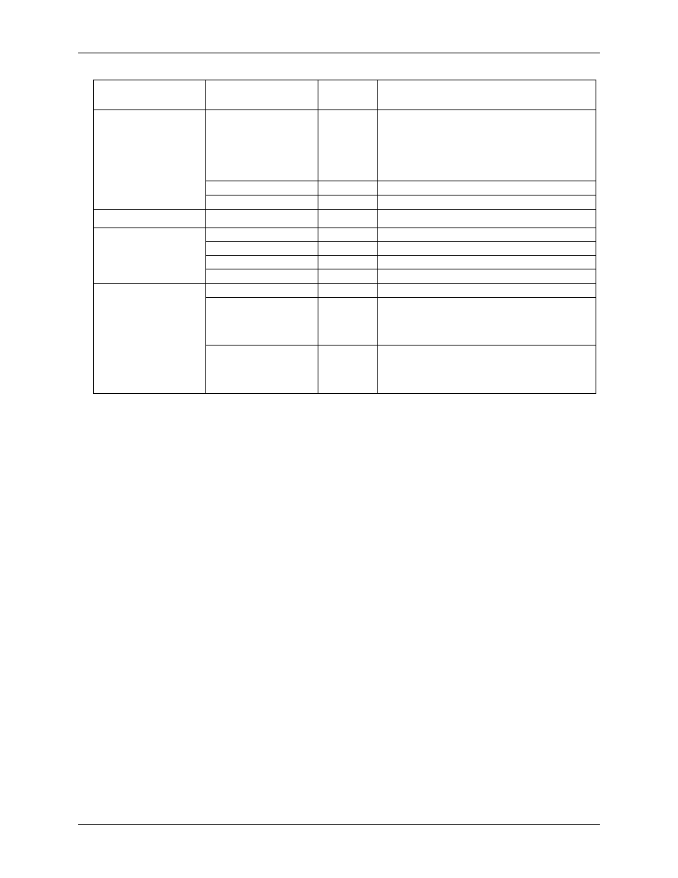
Component
Supported
Property/Command
Set/Get
Supported Values
MFGCAL{item}
Get
YEAR as yyyy; 20xx
MONTH as mm; 01 to 12
DAY as dd; 01 to 31
HOUR as HH; 01 to 23
MINUTE as MM; 01 to 59
SECOND as SS; 01 to 59
MFGSER
Get
Up to 8 hexadecimal digits
RESET/{value}
Set
DEFAULT, SYSTEM
DIO
Get
1 (number of ports)
DIO{port}
Get
8 (number of bits on the port)
DIR
Set/Get
IN, OUT
LATCH
Set/Get
0 to 255
VALUE
Set/Get
0 to 255
DIO{port/bit}
DIR
Set/Get
IN, OUT
LATCH
Set/Get
port number: 0
bit number: 0 to 7
port value: 0 to 255
bit value: 0, 1
VALUE
Set/Get
port number: 0
bit number: 0 to 7
port value: 0 to 255
bit value: 0, 1
Hardware features
8 single-ended analog input channels, numbered 0 to 7.
Analog input range is fixed at ±10 V.
1 digital port (8 bits). Each bit is individually configurable as input or output.
1 external digital trigger input.
External pacer input/output. This feature allows multiple devices to acquire synchronized samples.
1,024 bytes of nonvolatile EEPROM memory; used for storing configuration information, calibration
data, and user data.
RATE takes a float value. An error is generated if value set is less than the device minimum
sampling rate or greater than the device maximum sampling rate.
Bulk transfers:
o Bulk transfers from endpoint 1 IN are used for analog input scans.
o The bulk in max packet size is 64 bytes.
o The bulk transfer size must be a multiple of the USB maximum bulk packet size.
o Bulk transactions are complete when a packet is sent that is less than the max packet size.
When sending an integer multiplier of the max packet size of data during a transaction, include
an empty packet to indicate the end of the transaction.