MEGA Corp. MMP4-2 User Manual
Page 24
MMP 4-2
5 Nov 2011
SECTION 5
Water Pump Assembly
Contents
5-1
Description ………………………......... 5-1
Hydraulic Drive Motor …………...…… 5-1
Inspection and Service ...………………. 5-2
Parts Breakdown of Water Pump ..…….... 5-5
Repair ………………………………...
1-1
Disassembly .............................................. 5-7
Assembly ................................................... 5-8
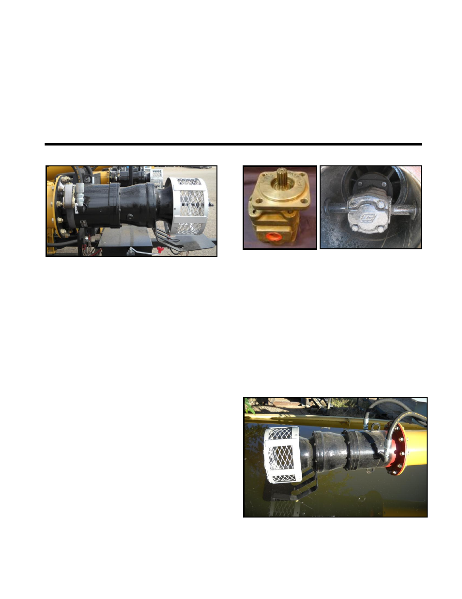
DESCRIPTION
The water pump assembly is comprised of;
hydraulic drive motor, water pump housing,
impeller, shaft and bearings and an inlet screen.
The water pump assembly uses hydraulic oil
flow produced by the engine driven hydraulic
oil pump to turn the hydraulic drive motor
which is directly coupled to the water pump
impeller. Water pump speed is controlled by
the hydraulic control valve and pressure relief
cartridge which diverts the oil flow to the inlet
port (pressure) of the hydraulic drive motor to
the return oil hose for the hydraulic system.
The pressure relief cartridge diverts excessive
oil pressure directly to the hydraulic return
hose, returning back to the hydraulic oil to the
tank for system protection.
HYDRAULIC DRIVE MOTOR
A gear-type hydraulic motor mounted inside
the water pump assembly. The hydraulic motor
receives hydraulic oil flow from the hydraulic
system controlled by the hydraulic control
valve at 1,900 - 2,800 PSI (13,000 – 19,300
kpa) and flow rates up to 35 GPM (135 lpm)
for operation. The hydraulic motor is coupled
directly to the water pump shaft and rotates in a
clockwise (CW) direction as viewed from the
inlet of the pump. The speed and volume of the
water pump is dependent on the engine RPMs,
[e.g: higher engine RPMs yields a higher
output volume of water].