MEGA Corp. MMP4-2 User Manual
Page 18
MMP 4-2
5 Nov 2011
SECTION 4
Basic Hydraulics System
4-3
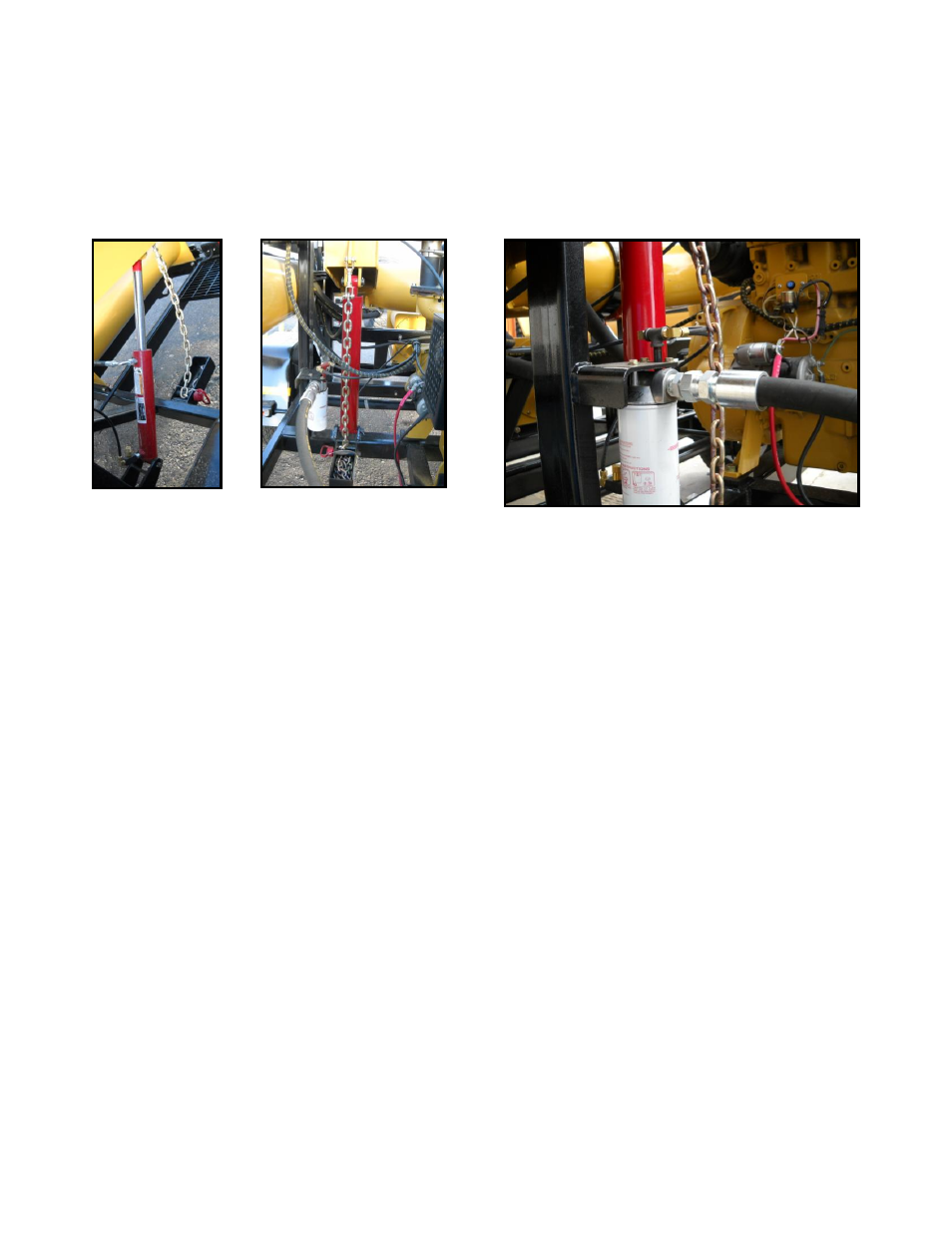
HYDRAULIC CYLINDERS
The 2 hydraulic cylinders are used for lifting
the inlet and discharge booms to either the
‘stow/travel’ position or to the ‘fill’ position.
When the boom control lever is operated in the
‘UP’ position the pressurized oil retracts the
cylinder and lifts the boom. The speed of the
lifting is controlled by metering valves attached
to the hydraulic control valve. There are safety
chains at each cylinder to prevent any
unwanted movement in the boom when it is
filled with water and as a safety precaution in
case the control valve lever is operated
accidentally. The cylinder operates in the
boom down mode by moving the control valve
lever to the ‘DOWN’ position, the weight of
the boom makes the cylinder extend. The
speed of the downward motion is controlled by
a fluid metering valve attached to the hydraulic
cylinder that restricts the fluid exiting the
cylinder causing a slow, controlled lowering of
the booms.
HYDRAULIC FILTER
The spin on hydraulic oil filter is in the return
to tank hydraulic circuit. All hydraulic oil
passing through the system passes through the
filter prior to the hydraulic oil cooler. The
filter is rated at 400 psi (2,758 kpa) and has a
provision for the cylinder lower plumbing. The
filter is rated at 10 microns. The filter housing
has a built in bypass valve to bypass the filter
element when the inlet pressure is too high or
the filter becomes restricted.