MEGA Corp. MMP4-2 User Manual
Page 16
MMP 4-2
5 Nov 2011
SECTION 4
Basic Hydraulics System
Contents
4-1
Description …………………………..... 4-1
Hydraulic Tank………………………….. 4-1
Hydraulic Pump………………………… 4-2
Hydraulic Control Valve……………...... 4-2
Water Pump Hydraulic Drive Motor .... 4-2
Hydraulic Cylinders ………………....... 4-3
Hydraulic Oil Filter.……………….…..
4-3
Hydraulic Oil Cooler……………….…. 4-4
Hydraulic Hoses ………………….….. 4-4
Inspection ……………………………... 4-5
Repair ……………………………….… 4-7
DESCRIPTION
The MMP 4 hydraulic system originates at a
hydraulic pump coupled to a CAT 3054B
Diesel engine. The system draws hydraulic oil
from a hydraulic tank mounted at the rear of the
MMP 4 frame through a inlet screen inside of
the tank and a shut off valve on the outside of
the tank. The hydraulic pump moves the oil to
a hydraulic control valve mounted to the right
side of the unit. The control valve diverts and
regulates the oil flow and pressure through the
MMP 4 system. The Hydraulic control valve is
used to control the raising and lowering of the 2
hydraulic cylinders attached to the inlet and
discharge booms. The hydraulic control valve
also controls the hydraulic drive motor inside
of the water pump at the end of the inlet boom,
this control feature is equipped with a detent to
allow the lever to stay in the ON position
during water pump operation and is equipped
with a pressure relief valve to protect against
over pressurization of the hydraulic system.
The return hydraulic oil is passed through a
hydraulic oil filter, oil cooler then a diffuser
mounted inside of the hydraulic oil tank.
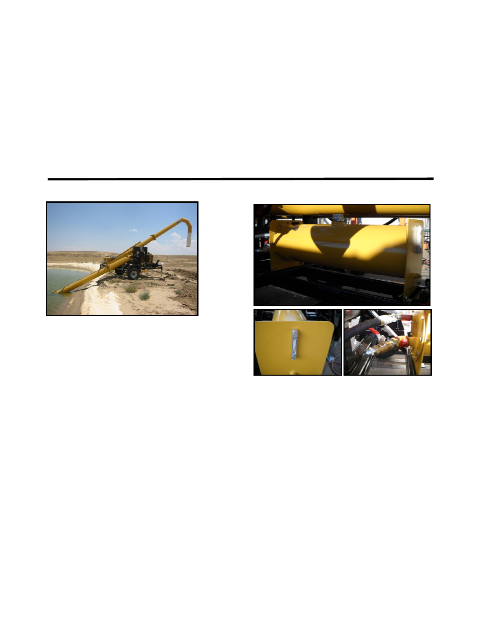
HYDRAULIC TANK ASSEMBLY
The hydraulic tank consists of an inlet screen,
return oil diffuser, internal baffle, shut off
valve, oil level sight gauge, reservoir cap and
breather. The system draws oil from the
bottom of the tank through an inlet screen to
pre-filter the oil. The shut off valve holds the
oil inside of the tank when servicing the
hydraulic system. The sight gauge is used as a
visual indicator of the hydraulic oil quality and
quantity. The Internal baffle allows for oil
movement with in the tank to evenly distribute
the return oil trough out the reservoir. The
return diffuser inside of the hydraulic tank just
below the normal oil level reduces the potential
for hydraulic oil foaming in the tank. The
reservoir cap and breather allow filling of the
hydraulic tank and prevent dirt and debris from
entering the hydraulic system.