Harken ECB Control Box Conversion for Single-Acting Cylinder Operation User Manual
Introduction, Understanding ecb terminal labeling, Conversion instructions
Converting a Standard Control Box to Operate Single-Acting Cylinders
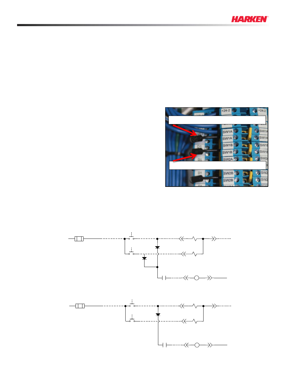
Example of diode connections on
double terminal blocks for ECB3
Diode supplying power to motor and valve (A) side
Diode supplying power to motor and valve (B) side
Introduction
In its standard configuration, the Electronic Control Box (ECB) is internally wired to operate the pump motor(s) and energize the valve(s). Generally,
customer supplied switches actuate the function motor(s) (furler, winch, etc.) and a valve in one of two directions:
Forward - Valve (A) side opens
Reverse - Valve (B) side opens.
If the ECB unit will be used to power a single-acting cylinder with a poppet-style solenoid valve, pump motor function is needed in only one direction
(A). A simple wiring change can be performed in the field to convert the ECB to operate the pump/open the valve when the (A) side is selected.
When the (B) side is selected, the valve releases (opens A to T), but the motor does not operate.
Understanding ECB Terminal Labeling
There are three (3) standard ECB configurations. ECB1 controls one (1) motor; ECB2 controls two (2) motors; ECB3 controls three (3) motors.
Connections for valves and terminal switches are made to SWxA and SWxB. Diodes are installed at the factory to connect the valve and switch
terminals (SWxA and SWxB) to motor terminals D1 (Motor 1), D2 (Motor 2), D3 (Motor 3).
Conversion Instructions
To convert the ECB internal wiring to allow for cylinder operation, perform the
following steps.
1. Open ECB cover.
2. Locate/select terminals on double terminal blocks to be used for cylinder
function switch wiring
Ex.: If cylinder is designated as Function 1, then switches are typically wired to
SW1A and SW1B.
3. Locate diode connecting selected terminal (SWxB) to D1, D2 or D3 on lower
half of double terminal block.
4. Using 1/8” slot screwdriver, loosen screws securing diode to SWxB and D1, D2
or D3 on double terminal block.
5. Remove diode and set aside or discard.
Removal of diode connecting SWxB to D1, D2 or D3 will prevent power from
going to the motor when (B) side switch is selected.
Note: The valve (B) side will continue to energize when the switch is selected. Diode removal only deactivates motor control.
6. Close and secure ECB cover.
Sample Schematics
Sample of schematic
with diode connecting
SWxB to D1
Sample of schematic
with no diode connection
between SWxB and D1
SOL3A
BLUE
BLK
WHT
VALVE3
A COIL / B COIL
PB3A
PB3B
SOL3B
2 A
CB3
+24-3
1
1
2
2
1
1
D1
SW3A
1N5400
M1
CR1
RED
1
PL1
1
PL1
2
2
MOTOR #1
CONTACTOR COIL
GREEN
D1
SW3B
1N5400
VALVE 3 (A COIL)
VALVE 3 (B COIL)
SOL3A
BLUE
BLK
WHT
VALVE3
A COIL / B COIL
PB3A
PB3B
SOL3B
2 A
CB3
+24-3
1
1
2
2
1
1
D1
SW3A
1N5400
M1
CR1
RED
1
PL1
1
PL1
2
2
MOTOR #1
CONTACTOR COIL
GREEN
VALVE 3 (A COIL)
VALVE 3 (B COIL)