A. setpoint, B. clock d. data logger, C. input/output – Greenheck Network Interface Controller for Tempered Air Products (476811) User Manual
Page 6: Menus
6
Network Interface Controller for Tempered Air Products
The controller is equipped with several menus to help guide users with altering program parameters. The
following menus can be accessed by pressing the
Prg
or
key. To enter the desired menu, press the
key.
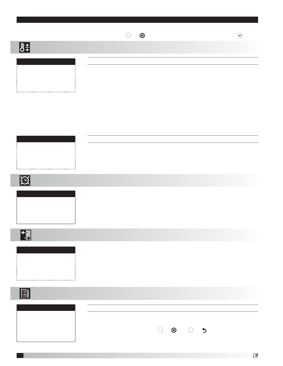
The Setpoint menu allows the user to view and adjust temperature related
parameters.
T
HIS
SCREEN
DISPLAYS
THE
LOW
SUPPLY
AIR
TEMPERATURE
LIMIT
.
If the unit supply air temperature falls below Supply Air Low Limit for a period of
Alarm Delay, the unit will do one of the following based on the Alarm Function.
•
Alarm Only: Sends alarm via BMS.
•
Alarm and Open NO3: Sends an alarm and opens NO3 (Unit Start/Stop
command) even if the BMS start/stop command is active.
•
Disable: Disables the supply air low limit function.
The purpose of the supply low limit is to protect the building and contents from
cold supply air. It is NOT designed to protect the air handling unit.
If the unit does not have cold or hot water coils, it should not need additional
protection from freezing. If the unit does have cold or hot water coils, field
provided coil freeze protection may be necessary.
T
HIS
SCREEN
DISPLAYS
CO2
SENSOR
SETUP
.
This screen only appears if the unit is equipped with a CO2 sensor.
This screen is used to match the settings of the CO2 sensor to the network
interface controller.
Menus
Supply air low limit
Alarm when supply is
below
35.0°F
Alarm delay:
300s
Alarm Function:
Alarm
Only
CO2 Sensor Setup
CO2 Output
2-10VDC
Scaling:
2vdc 500
ppm
10vdc 1500ppm
A. Setpoint
The Clock screen allows the user to adjust the time and date.
Set Date & Time
Day: Monday
Date: 01/31/10
Hour: 15:30
The Clock/Scheduler menu allows the user to view and alter the time and date.
B. Clock
D. Data
Logger
To manually control I/O values, go to the Service menu > Overrides.
Similar screens appear for all controller inputs and outputs.
T
HIS
SCREEN
IS
AN
EXAMPLE
OF
A
RECORDED
ALARM
.
The unit conditions are displayed for past alarm events. The date, time,
temperatures and unit status are recorded.
To clear recorded alarms, press
Prg
or
and
Esc
or
simultaneously.
Analog Input
B4-Supply Air Temp
Input B04:
70.0°F
13:21:04 10/05/10
OA Sensor
Outside Air T:
-623.3
Supply Air T:
70.0
C. Input/Output
The Input/Output menu allows the user to quickly view the status of the controller
inputs and outputs.
The Data Logger menu allows the user to view past alarms.
The Clock menu allows the user to view and alter the time and date.
The Setpoint menu allows the user to view and adjust temperature related
parameters.
®