Greenheck Network Interface Controller for Tempered Air Products (476811) User Manual
Page 2
2
Network Interface Controller for Tempered Air Products
Input Points (Max 5)
Output Points Digital (Max 5)
Output Points Analog (Max 3)
Cold Coil Temp
Call for Heat Stage 1
Heat Output
Return Air Temp
Call for Cool Stage 1
Cool Output
Exhaust Discharge Temp
Call for Cool Stage 2
Supply VFD
Outdoor Air After Wheel Temp
Occupied Unoccupied
Exhaust VFD
Dirty Filter Status
Remote Exhaust Fan
Energy Wheel VFD
Rotation Status
Call for HGRH
Return Air Damper
CO
2
Sensor
Alarm
User Defined
Supply VFD Monitor Signal
User Defined
Exhaust VFD Monitor Signal
User Defined
Room Temp
Frost Status
Econ Status
Input/Output Points
Standard Input/Output points are Supply Air Temp, Outside Air Temp and Fan Proving Status. The following are
optional I/O points. See Network Interface unit diagram to see job specific I/O.
Display Use
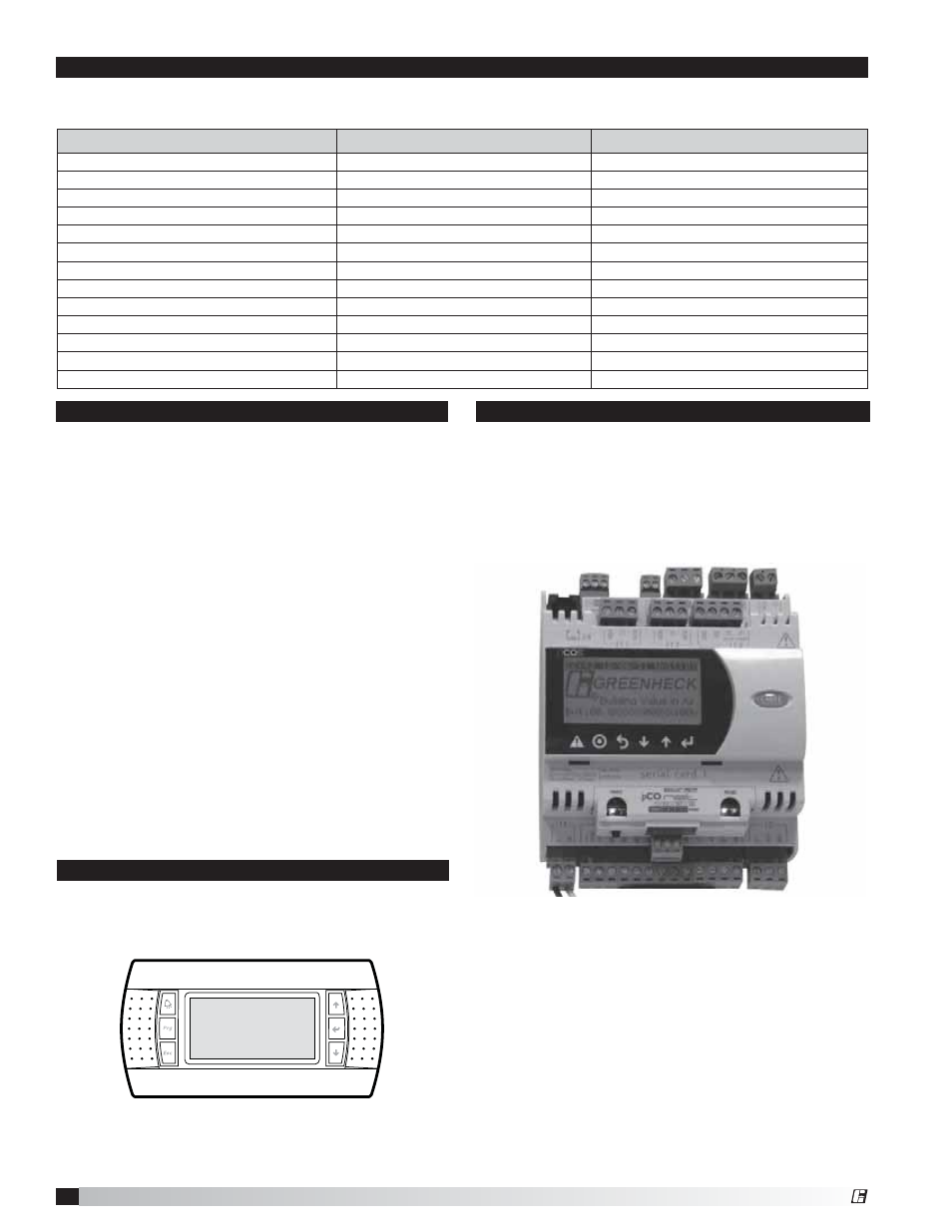
The network interface controller is located in the unit
control panel. The face of the controller has six keys,
allowing the user to view unit conditions and alter
parameters. The network interface controller is pre-
programmed with easy-to-use menus.
The network interface controller will monitor the unit
conditions for alarm conditions. Upon detecting an
alarm, the controller will record the alarm description,
time, date and available temperatures for user review.
An optional digital output is available for remote
alarm indication. Alarms are also communicated via
BMS.
• Temperature Sensor Alarm: Network interface
controller will send an alarm in the case of a failed
air temperature sensor.
• Supply Air Low Limit: If the supply air temperature
drops below the supply air low limit (35°F), the
network interface controller can do one of the
following based on user setup.
-
Alarm Only: Sends alarm via BMS.
- Alarm and Open NO3: Sends an alarm and turns
the unit run command off, even if BMS run
command is active.
- Disable: Disables the supply air low limit
function.
Alarms
Remote Display Panel (Optional)
A display panel allows for remote monitoring and
adjustment of parameters, allowing ease of control
access without going outdoors.
A remote mounted display is also available, which
connects via the J4 port. A six-wire patch cable is
needed.
®