GAI-Tronics MS05-101 Desktop Master Station consisting of Subset, Amplifier and Enclosure User Manual
Page 5
Pub. MS05-101iom.2
Model MS05-101 Desktop Master Station
Page:
5 of 11
\\86h27g1-fs\iomdocs\opnotes -- released\mi05-00x merge-isolate cabs\ms05-101.dir\ms05-101iom2.doc
03/09
Switch Setting Examples
Switch
S2
Switch
S1
Master Station
Address
0 1
1
0 2
2
0 3
3
0 4
4
0 5
5
0 6
6
0 7
7
0 8
8
N
OTE
: The factory default setting is 01 since typically there is only one master station per system.
N
OTE
: The switch setting is recognized only when either the I/O Controller is powered up, or when the
R
ESET
button is pressed. Momentarily press the R
ESET
button each time a switch is changed.
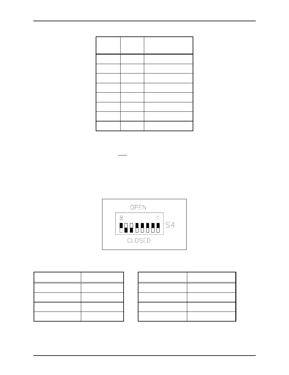
DIP Switch Settings
The I/O controller switch S4 is an 8-position DIP switch that is used to set the data baud rate. This switch
is factory set and should not be changed. If replacing the I/O controller, be sure to set the switch as
follows:
Figure 2. S4 DIP Switch
Switch Position Open/Close
Switch Position
Open/Close
S4-1 Open
S4-5 Open
S4-2 Open
S4-6 Close
S4-3 Open
S4-7 Close
S4-4 Open
S4-8 Open
Momentarily press the R
ESET
button each time a switch is changed.
- 370-201, 372A Interface Amplifier Assembly (10 pages)
- 13314-001 and 13314-002 Div. 2 Hazardous Area Speaker Assembly using 13314 Driver (3 pages)
- 230-001 Pole-Mounting Kit (3 pages)
- Electro Sound Electro-Sound Communication System (9 pages)
- 13314-004 Div. 2 Hazardous Area 100-Volt Horn Driver (5 pages)
- XGM003A Gooseneck Microphone Kit (5 pages)
- XGM003A Gooseneck Microphone Kit (2 pages)
- XGM003A Gooseneck Microphone Kit (26 pages)
- 9974 Junction Box (5 pages)
- 232-001 Pole Mounting Kit (3 pages)
- 13411-001 and 13411-002 Replacement Voice Coil / Diaphragm Assemblies (5 pages)
- 726-101 Single Party Desktop Subset (4 pages)
- 726-101 Single Party Desktop Subset (5 pages)
- 478-002 Centra-Page Desktop Subset (6 pages)
- 239WM-002 Slim Wall-Mount Stanchions (4 pages)
- 210-001 Corridor Telephone (10 pages)
- 239WM-002 Slim Wall-Mount Stanchions (10 pages)
- 239WM-002 Slim Wall-Mount Stanchions (5 pages)
- 239WM-002 Slim Wall-Mount Stanchions (6 pages)
- 239WM-002 Slim Wall-Mount Stanchions (4 pages)
- Speaker / Horn Installation for GAI-Tronics Communication System (8 pages)
- 700 Series 120 V AC Page/Party Systems (10 pages)
- 700 Series 24 V DC Page/Party Systems (14 pages)
- 703-002 Multi-Party 24 V DC Amplifier Enclosures (13 pages)
- 703A Indoor Multi-Party 115 V AC Amplifier Enclosure (8 pages)
- 703A Indoor Multi-Party 115 V AC Amplifier Enclosure (3 pages)
- 723-001 Remote Handset / Speaker Amplifier (3 pages)
- 723-003 24 V DC Remote Handset/Speaker Amplifier (7 pages)
- 237-001 Plug-in Power Supply for Telephones (3 pages)
- 733-002 Single Party 24 V DC Amplifier Enclosure (13 pages)
- 7855-001 Explosion-proof Handset Stations (13 pages)
- 7855-002 24 V DC Explosion-proof Page/Party Handset Stations (14 pages)
- 670-001 Explosion-proof Page/Party Speaker Station (9 pages)
- 670-002 24 V DC Explosion-proof Page/Party Speaker Station (10 pages)
- 13351 Integral Loudspeakers (5 pages)
- 305-001 Line Balance Assembly (3 pages)
- 272-001 Intrinsically-Safe Telephones (13 pages)
- 713-102 24 V DC Page/Party Remote Speaker Amplifier (5 pages)
- 263-000 Isolation Barrier Unit (I.S. Phone) (14 pages)
- 774-001 Portable Station Enclosure (Page/Party) (5 pages)
- 234SBA 234SBA Stanchion Broadcast Assembly (12 pages)
- 491-204 Mine Dial / Page Phone (10 pages)
- 773-001 Outdoor Jack Station (Page/Party) (3 pages)
- 491 Series Mine Dial / Page Phone Interface Cabinet (23 pages)
- 268-001 Intrinsically-Safe Telephone Rack-Mount System (14 pages)