Connections to the merge/isolate cabinet – GAI-Tronics MS05-101 Desktop Master Station consisting of Subset, Amplifier and Enclosure User Manual
Page 3
Pub. MS05-101iom.2
Model MS05-101 Desktop Master Station
Page:
3 of 11
\\86h27g1-fs\iomdocs\opnotes -- released\mi05-00x merge-isolate cabs\ms05-101.dir\ms05-101iom2.doc
03/09
Connections to the Merge/Isolate Cabinet
1. Locate the Termination PCBA in the lower left corner of the merge/isolate cabinet.
2. Connect the master station cable to TB6 in the cabinet. Refer to the Wiring Terminations Table.
A 9-pair cable (No. 18–20 AWG) is recommended for this connection.
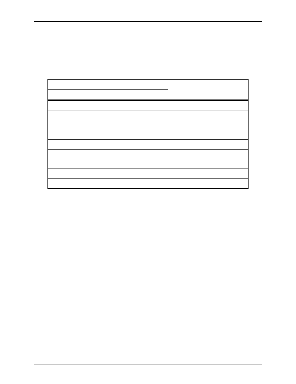
Wiring Terminations Table
Terminals
Master Station
Merge/Isolate Cabinet
Function
TB3-23 and TB3-24
TB6-1 and TB6-2
RS-485 data line (+ /-)
TB3-25
TB6-3
Data ground
TB1-10 and TB1-11
TB6-5 and TB6-6
Page monitor (See note.)
TB1-8 and TB1-9
TB6-7 and TB6-8
Page line (See note.)
TB2-12 and TB2-13
TB6-9and TB6-10
Party Line 1
TB2-14 and TB2-15
TB6-11 and TB6-12
Party Line 2
TB2-16 and TB2-17
TB6-13 and TB6-14
Party Line 3
TB2-18 and TB2-19
TB6-15 and TB6-16
Party Line 4
TB2-20 and TB2-21
TB6-17 and TB6-18
Party Line 5
N
OTE
: If connecting to Model MI05-101 Merge/Isolate Cabinet, jumper the page line (TB1-8 and
TB1-9) to the page monitor line (TB1-10 and TB1-11). If these lines are not tied together, the master
station speaker will not broadcast.