Jumper positions, Jumper position table, Line input gain select switches – GAI-Tronics IDA1000A DC Remote Adapter Installation and Service Manual User Manual
Page 19
Model IDA1000A DC Remote Adapter
Installation
15
01/05
Jumper Positions
The IDA circuit board contains nine jumpers, JU1 through JU5, and JU10 through 13. See board layout
in the Main Circuit Board section. The default setting provides normal operation. It should be changed
only for special applications.
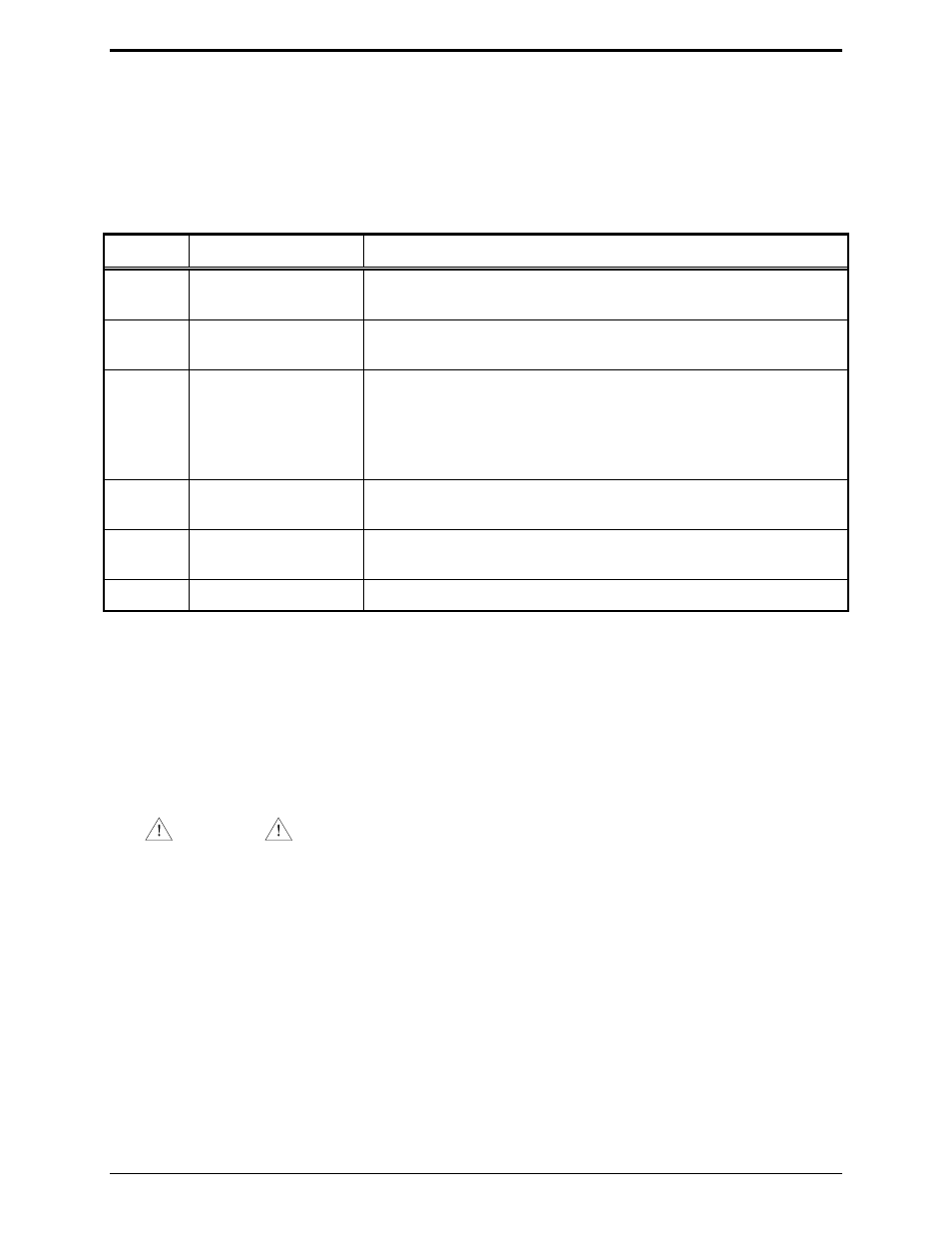
Jumper Position Table
Jumper Position
Function
JU1
3
1*
Line driver disable
Line driver enable
JU2
Out
In*
4-wire (if XDA0001A option is installed)
2-wire
JU3
Out*
In
SW1-3 Up - Line input range: 32 mV ac to 150 mV ac
SW1-3 Down – Line input range: 150 mV ac to 400 mV ac
SW1-3 Up – Line input range: 400 mV ac to 1.7 V ac
SW1-3 Down – Line input range: 1.7 V ac to 4.5 V ac
JU4
A
B*
High output for F1
Low output for F1
JU5
A
B*
High output for F2
Low output for F2
JU10-13
Out*
Special applications only.
*Indicates the default positions.
Line Input Gain Select Switches
For
SW1
sections 2 and 3, the default setting is down. These should be changed only if one of the remote
units has wire line losses of 10 dB or more. Select a gain setting to compensate for the unit with the most
loss. Adjust all other units to give identical transmit levels. To make adjustments:
1. Apply a 1000 Hz tone at the desired line level, e.g. 0 dBm at the remote end of the wire line to be
tested.
CAUTION
Do not exceed the recommended operating level of the line. Consult the line provider for this
information.
2. Measure and record the level at the remote adapter end with the adapter connected to the line. Do this
for each line attached.
3. Select the gain that best compensates for the line with the most loss. Start with the desk set that has
the most line loss and use the recommended mic input level from the desk set adjustment instructions.
Adjust the line driver on each desk set to obtain a 2/3 system deviation (nominally 80 to 165 mV ac).