Radio and accessory connection chart – GAI-Tronics IDA1000A DC Remote Adapter Installation and Service Manual User Manual
Page 17
Model IDA1000A DC Remote Adapter
Installation
13
01/05
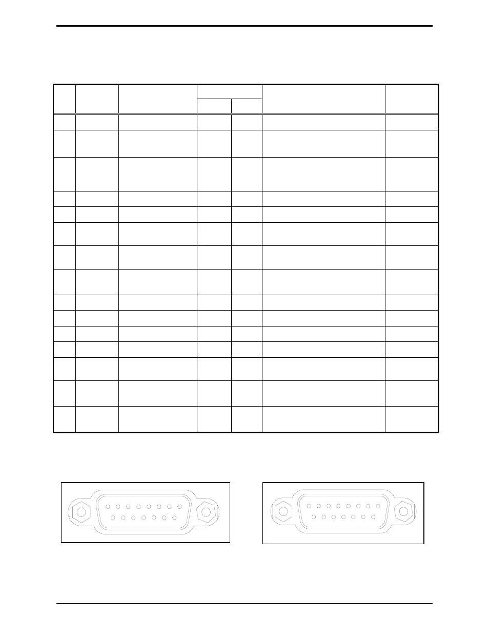
Radio and Accessory Connection Chart
Radio connections are made via P1-1 to P1-15. J3-1 to J3-15 accessory connections correspond
numerically and functionally.
Pin
Wire
Input/ Output
Nominal
#
Color
Description
Radio
Acc.
Range
Default
1
Blk/Wht
dc+ (not used)
JU12
Power input
B+ V dc
2
Blu/Wht
Duplex control
JU10
I
I
Enable high (+5 V dc)
Disable low (0 V dc) RX audio
0 V dc
3
Green
RX audio +
I
O
Range 1: 32 mV–400 mV
RMS
Range 2: 400 mV–4.5 V
RMS
See Jumper Position Table.
300 mV
RMS
4
Black
Mic low (AGND)
0 V dc
5
Wht/Blk
Not used.
6
White
PTT (push-to-talk)
O
I
Active low (GND)
(B+ unkeyed)
0 V dc
7
Orange
Monitor
O
I
Active low (GND)
(B+ unkeyed)
0 V dc
8
Red
F1
O
I
JU15
Low (0 V dc) or high (+5 V dc)
0 V dc
9
Red/Wht
dc– (not used)
JU13
Power input
0 V dc
10
Grn/Wht
Not used
11
Grn/Blk
RX audio -
I
O
12
Blue
TX audio (Mic Hi)
O
I
32 mV–800 mV
RMS
560 ohms
80 mV
RMS
13
Blu/Blk
PTT (push-to-talk)
O
I
Active high (B+) (GND
unkeyed)
B+ V dc
14
Org/Blk
Monitor
JU11
O
I
Active high (B+) (GND
unkeyed)
B+ V dc
15
Rd/Blk
F2
O
I
JU14
Low (0 V dc) or high (+5 V dc)
0 V dc
*N
OTE
: Colors apply to the supplied GAI-Tronics cable.
Possible accessories include external speaker, telephone interconnect, local desk set, tone remote adapter,
or paging encoder.
9
1
15
8
Figure 4. P1 Radio Connector Mating Side Pin
Contacts
15
8
9
1
Figure 5. J3 Accessory Connector Mating Side
Socket Contacts