Cable installation safety considerations, Power connections, Power connections pin-out – GAI-Tronics IDA1000A DC Remote Adapter Installation and Service Manual User Manual
Page 14
Installation
Model IDA 1000A DC Remote Adapter
01/05
10
Cable Installation Safety Considerations
Interconnecting, communications, and Class 2 dc power cables should be separated from electrical light
or other Class I circuits by at least 2 inches. The exception is where Class I wiring or power circuits are
run in a raceway, or are metal-sheathed or metal-clad, or are permanently separated from the conductors
of the other circuitry by a continuous and firmly fixed nonconductor such as porcelain tubes or flexible
tubing in addition to the insulation on the wire. Communications cables and in-building wiring should be
listed and marked for the purpose according to NEC Article 800.
Telephone Line Lightning and Over-voltage Protection
For maximum surge and lightning protection, building primary (over-voltage) protectors should be
installed at the point where the phone lines enter the radio equipment building. Primary protectors are
usually required by local codes and should be provided by your local exchange carrier.
The Model IDA1000A has over-current phone line fuses F2 (main) and F3 (4-wire option board), which
protect against occasional extreme fault conditions that may get past the primary protectors. An example
of such a fault condition is a power line cross. If the fuse requires replacement, replace it with the same
type Bussmann C515S 1.25A SB fuse.
Power Connections
Connections should be made to a 10.5 to 16 V dc source capable of supplying up to 300 mA. An optional
120 V ac wall transformer (Part No. 3308-00750-00) should be used if a suitable dc source is not
available.
The Model IDA1000A provides active low outputs referenced to system ground (negative ground
system). To interface with a positive ground radio station, or a radio needing active high signals, requires
relays or opto-isolators, which translate the adapter outputs.
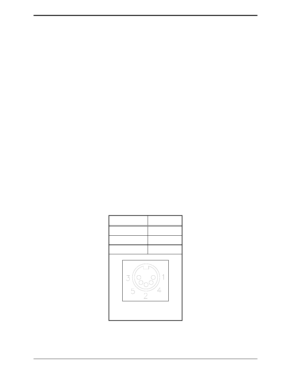
Power Connections Pin-out
Pins
Position
Pins 3 and 5
+IN
Pins 1 and 4
-IN
Pin 2
Battery +
Figure 3. Optional 5-Pin DIN
Power Supply