Technical specifications, Dimensions – FSR TwisterPro User Manual
Page 7
13
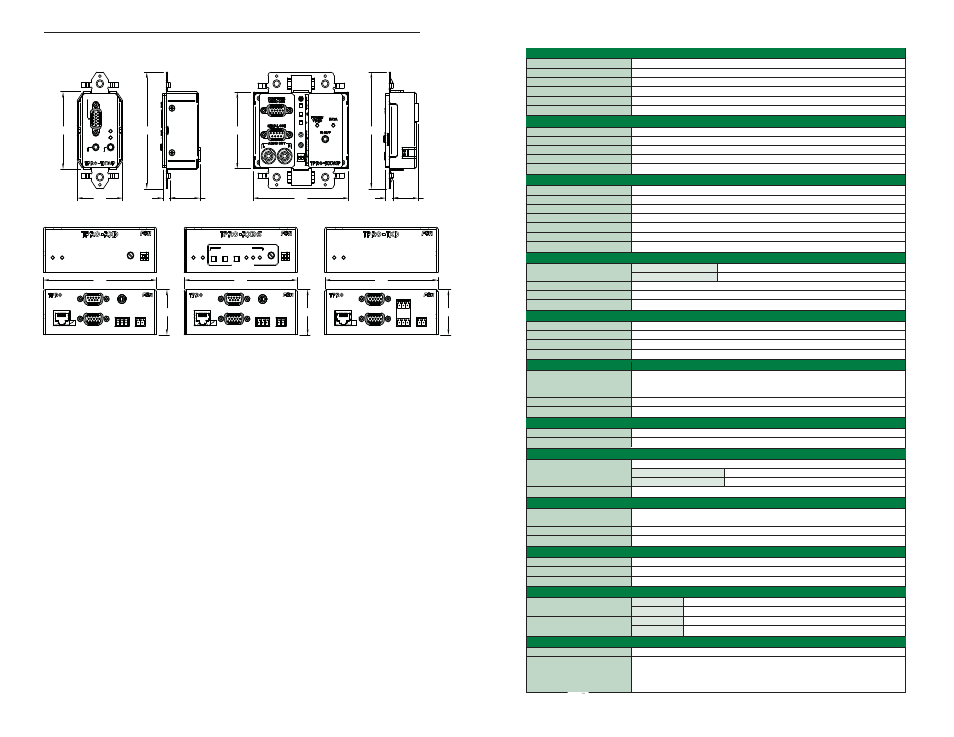
DIMENSIONS
1.70
4.09
1.12
.27
COMPUTER VIDEO IN
POWER/
VIDEO
DATA
AUDIO IN
2.72
.95
.27
4.09
3.56
IR SENSOR
2.69
Computer A/V, IR, RS-232 Receiver
Power/
Video Data
Gain
Boost
Vid IR
On
Gain
Boost
Vid IR
On
Computer A/V, IR, RS-232 Receiver
Computer A/V, IR, RS-232 Transmitter
Power/
Video Data
Power/
Video Data
Picture Adjust
Skew Compensation
Left
Right
Next
Channel
UTP Input
from TPRO
Transmitter
UTP Input
from TPRO
Transmitter
UTP
PWR
OUT
Red =
Overload
UTP
PWR
OUT
Red =
Overload
Serial Out
Computer Video Out
Serial Out
Computer Video Out
Power 24VDC
.19A+TPRO-TX
Out
L Gnd R
Audio
Power 24VDC
.12A+TPRO-TX
Out
L Gnd R
Audio
Out
IR
Out
IR
TPRO-TXWP
TPRO-RXWPD/TPRO-RXWPDS
4.22
1.59
APPROXIMATE DEPTH: 4.25
TPRO-RXD
4.22
1.59
4.22
1.59
APPROXIMATE DEPTH: 4.25
TPRO-RXDS
APPROXIMATE DEPTH: 4.25
TPRO-TXD
UTP Input
to TPRO
Receiver
UTP
PWR
OUT
Red =
Overload
Local Monitor Out
Computer Video In
Power 24VDC
.09A+TPRO-RX
Audio In
L Gnd R
IR
In Gnd In
RS232
14
RGB VIDEO INPUT
Connector
1-HD-15 female connector
Signal Type
1 RGBHV, RGBS, RGsB, RsGsBs,Component, S-video or Composite
Maximum Resolution
1920 X 1080 (1080P)
Impedance
75
Ω
Level (nominal)
Analog 0.7V p-p
Level (maximum)
+-1.0 V
RGB VIDEO OUTPUT
Connector
1-HD-15 female connector (Brick models have an additional HD-15 loopback connector)
Signal Type
Same as input
Gain
Unity
Impedance
75
Ω
Sync output
5V into Hi Z, 2.2V into 75
Ω
AUDIO INPUT
Connector
1-3.5 mm stereo mini jack (wallplates), 3 pin Phoenix plug (bricks)
Signal type
Stereo unbalanced
Level (nominal)
0.25V RMS -10dBm
Level (maximum)
1.1V RMS, +3dBm
Impedance
50 k
Ω
Encoding
Full stereo 24 bit, 96kHz sample rate
Frequency response
20Hz-15kHz +-0.5dB
AUDIO OUTPUT
Connector
Wallplate model receivers
2 RCA jack connectors
Brick model receivers
3 pin pluggable screw terminals
Signal type
Stereo unbalanced
Impedance
50
Ω (Intended to drive a 600Ω or greater load)
Gain
Unity +- 1.5dB
CONTROL ADJUSTMENTS
Delay Adjust
Independent for R, G and B delay (Skew models only)
Delay range
0-62 ns (Skew models only)
Video Boost Switch
Dip switch (OFF 0-800’/ON 200-1000’)
Gain control
Manual combined control for RGB
RS-232 DATA INPUT
Number/Type
One DB-9 female connector. (3 pin Phoenix plug on brick models) DCE type connection for
direct connection to a PC serial port included on two gang transmitters only. Must order
TPRO-Serial DB-9 accessory harness for one gang transmitters.
Handshaking
Local loopback only (Models with DB-9 connectors only)
RS-232 type
Unidirectional (data transmission from transmitter to receiver only)
RS-232 DATA OUTPUT
Number/Type
One DB-9 male connector. DTE type connection for direct connection to peripheral.
Data Rate
0-19.2k baud
INFRARED INPUT
Number/Type
Both models have internal sensor logically OR’d with hardwired input.
T-PRO TX brick models
One 4 pin pluggable Phoenix connector
T-PRO-TX wallplate models
One C-grid SL 5-pin connector on the back of the unit.
Compatibility
Compatible with most IR outputs designed to drive an IR emitter LED.
INFRARED OUTPUT
Number/Type
One3.5 mm mini jack, center positive. All TPRO-RX models
(Use FSR IR-EC1-6 single or IR-EC2-6 dual emitter accessory.)
Output Switch
Dip switch (Normal 12 mW/High 60mW)
Carrier Range
40 kHz, custom frequencies available per request.
POWER REQUIREMENTS
TPRO-RX Receivers
[email protected] (Skew models are [email protected])
TPRO-TX Transmitters
[email protected]
Power supplies are optional. Use FSR PS-24DC-500MA
MECHANICAL
Model
Dimensions (inches)
Shipping weight lbs.
Transmitter enclosure
Brick
4.22 X 1.59 X 4.10
Wall plate
1.70 X 4.09 X 1.46
Receiver enclosure
Brick
4.22 X 1.59 X 4.10
Wall plate
3.56 X 4.09 X 1.29
GENERAL
UTP cable wiring standard/ type
EIA / TIA-568B CAT5, 5E, 6
0-1000 ft with a single power supply (Up to 600’ when powered at transmitter. Up to 1000’
Recommended transmission range
when powered at receiver. When using a TPRO-HUB with included power supply:
The maximum distance to a transmitter is 1000’. The maximum distance to a receiver is 600’ *
* A distance of up to 1000’ can be achieved by adding an additional power supply at the receiver
TECHNICAL SPECIFICATIONS
3