Hd-15 connector pinout, Audio pinout, External ir sensor and emitter pinout – FSR TwisterPro User Manual
Page 6: Rj-45 jack front views, Hd-15 input connector pinout, As viewed from rear of unit)
11
HD-15 Connector Pinout
HD15 connector
1.Red / Pr / R-Y
2.Green / Y
3.Blue / Pb / B-Y
4.ID2 (Grounded)
5.NC
6.GND (Red)
7.GND (Green)
8.GND (Blue)
9.NC
10.GND
11.GND
12.NC
13.H sync (or composite sync for RGBS)
14.V sync
15.NC
Audio Pinout
LEFT
GROUND
RIGHT
LEFT
RIGHT
GROUND
AUDIO IN
IR SENSOR
LEFT
GROUND
RIGHT
Power 24VDC
.09A+TPRO-RX
Power 24VDC
.19A+TPRO-TX
Out
L Gnd R
Audio
Out
IR
LEFT
GROUND
RIGHT
AUDIO OUT
L
R
Wall plate style Transmitter
Wall plate style Receiver
Brick style Transmitter
Brick style Receiver
Audio In
L Gnd R
IR
In Gnd In
RS232
1
5
11
15
6
HD-15 Input Connector Pinout
(as viewed from rear of unit)
12
IR
EMITTER
(CUSTOMER
PROVIDED)
IR OUT
1/8” MINI JACK CONNECTOR
ON BRICK OR WALLPLATE STYLE
RECEIVERS
1 W/Orange
2 Orange
3 W/Green
4 Blue
5 W/Blue
6 Green
7 W/Brown
8 Brown
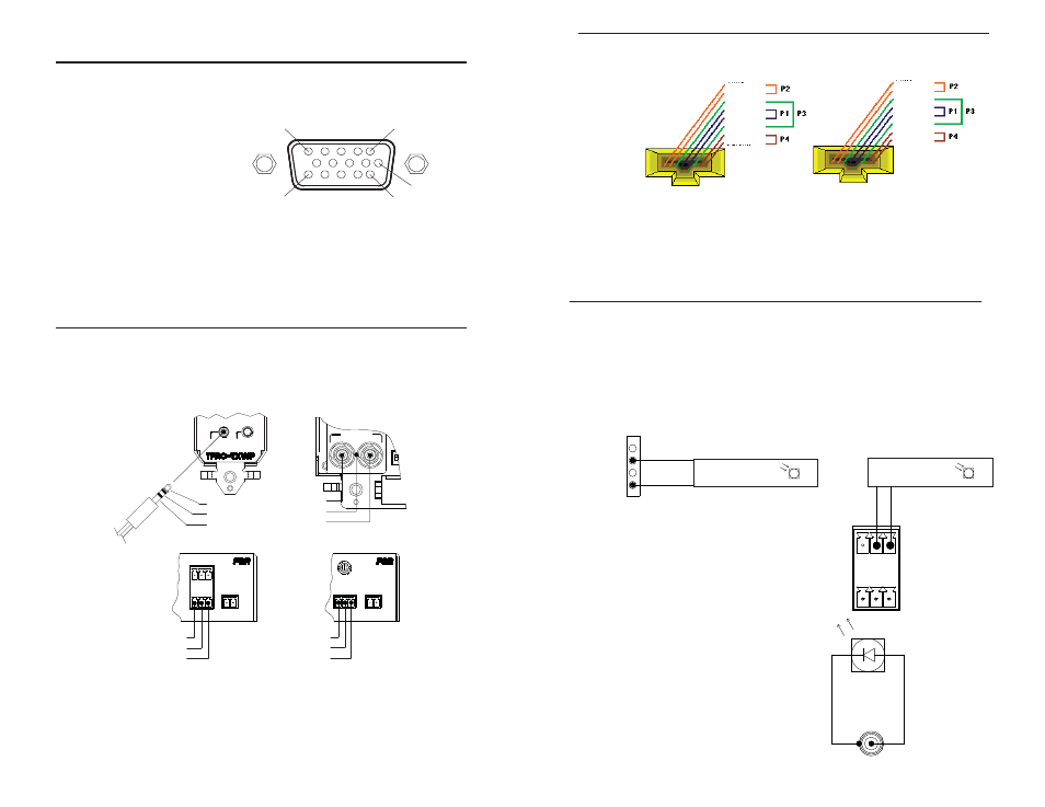
EIA/TIA568B
Wiring Standard
RJ-45 JACK FRONT VIEWS
Use the EIA / TIA 568B wiring standard only. Do not use a cross-
over type cable. A mis-wired cable could destroy the unit and void
the warranty.
External IR Sensor and Emitter Pinout
TX
IR INPUT
+5
GND
IR
CONTROL SYSTEM
(CUSTOMER PROVIDED)
IR CONTROL SYSTEM
OUTPUT
IR CONTROL SYSTEM
OUTPUT
CONNECTOR ON REAR OF ONE GANG
WALL PLATE STYLE TRANSMITTER
CONNECTOR ON BRICK STYLE TRANSMITTER
IR
In Gnd In
RS232
1 W/Orange
2 Orange
3 W/Green
4 Blue
5 W/Blue
6 Green
7 W/Brown
8 Brown