3 alarm configuration, Sensor, 2 alarm output – Q-See QSEE H264 User Manual
Page 40
78
79
Relay Specification
Model:
JRC-27F
Material of the contact
Silver
Rating (Resistance Load)
Rated switch capacity
30VDC 2A, 125VAC 1A
Maximum switch power
125VA 160W
Maximum switch voltage
250VAC, 220VDC
Maximum switch currency
1A
Insulation
Between contacts with same polarity 1000VAC 1minute
Between contacts with different
polarity
1000VAC 1minute
Between contacts and winding
1000VAC 1minute
Surge voltage
Between contacts with same polarity 1500V (10×160us)
Length of open time
3ms max
Length of close time
3ms max
Longevity
Mechanical
50×106 times (3Hz)
Electrical
200×103 times (0.5Hz)
Temperature
-40°C ~+70°C (-40°F to +158°F)
8.2 ALARM OUTPUT
The alarm output port should not be directly connected to a higher power load (greater than
1A) to avoid high current which may damage the relay. Use the co-contactor to establish the
connection between the alarm output port and the load.
• 2 way relay alarm output (NO contact). Provides external power to external alarm device.
• To avoid overloading, please read the following relay parameters sheet carefully.
• RS485 A/B cable is for the A/B cable of the PTZ camera(s).
PICTURE 8-3
PICTURE 8-4
PICTURE 8-5
8.3 ALARM CONFIGURATION
Alarm configuration allows the DVR to begin recording based on input from other remote
sensors such as infrared motion detectors or contact alarms which are connected to it.
There are five submenus;
Sensor, Motion, Video Loss, Other, and Alarm Out.
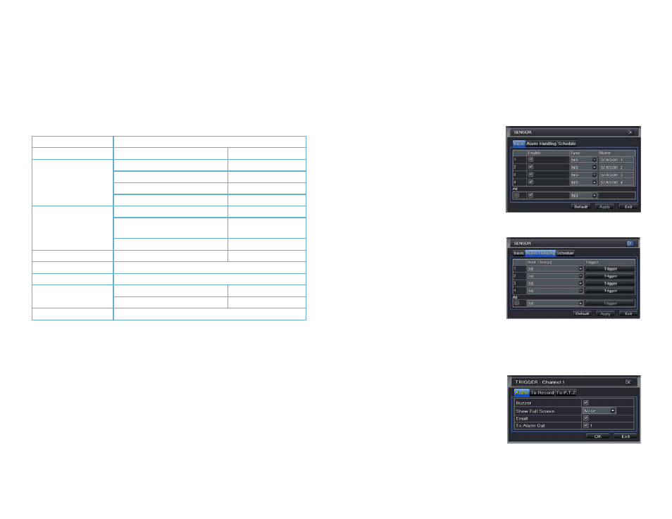
SENSOR
In this window you can setup optional external sensors to cause the DVR to begin recording.
There are three tabs in this window:
Basic, Alarm Handling and Schedule.
Basic Tab
This allows you to enable the input from
attached sensors. You can also identify the
sensors by name for ease in determining
location.
Set the alarm type according to whether the
alarm is NO (Normally Open) or NC (Normally
Closed). See your alarm’s manual for details.
Alarms can be individually configured or
globally set using the All button.
Alarm Handling Tab
Configure how you want the DVR to handle
the input from an activated alarm. Each
sensor input can be set to launch individual
sequences of action or they may be globally
set through the All button to have the same
results.
Hold Time: determines the time allowed
between consecutive alarm events.
If the alarm is triggered again within
this time, it will be treated as a single
event and the DVR will continue
recording before stopping.
Trigger: This is what the DVR will do once
activated by an alarm. Selecting
Setting will open a new window with
three tabs;
Alarm, To Record, To
PTZ
Alarm allows you to set whether a
buzzer will sound, which camera (if
any) will display in full screen mode,
whether an e-mail will be sent and
whether a signal will be sent via the
ALARM OUT port.